Bolt

a technology of bolts and bolts, applied in the field of bolts, can solve the problems of high fastening torque in order to secure conductivity, conduction failure, and coating cannot be completely peeled, and achieve the effects of reducing conduction failure, high conductivity, and reliable coating peeling

Active Publication Date: 2018-02-27
AOYAMA SEISAKUSHO CO LTD
View PDF41 Cites 5 Cited by
  • Summary
  • Abstract
  • Description
  • Claims
  • Application Information

AI Technical Summary

Benefits of technology

[0014]The bolt according to the first aspect of the present invention includes a coating peeling part which is formed at a tip end of an axis part, and the coating peeling part is designed to include: crushing parts having a trapezoidal top part and having a flank which is projected at a different angle with respect to the flank of the regular screw part; and a protruding part which is arranged adjacent to the crushing parts and whose top part projects beyond the outer diameter of the regular screw part. This enables peeling of the coating near the screw thread of a nut by the crushing part and further peeling of the coating near the valley bottom of the nut by the protruding part, thereby making it possible to completely remove coating. Also, this removed coating is designed to be discharged from a space part which is formed between the crushing part and the nut, thereby making it possible to suppress a conduction failure generated due to the remaining peeled coating. Further, the screw thread projected in the coating peeling part causes plastic flow within the nut, resulting in a smaller space part near the valley bottom of the nut. Therefore, the peeling of the coating by the protruding part is more securely occurs. In addition, since the regular screwing part is more firmly contacted with the nut at the time of completion of fastening, reliable coating peeling and high conductivity can be secured even when the bolt is fastened with a low torque.
[0015]According to the second aspect of the present invention, the protruding part is formed between the crushing parts so that the above-described coating peeling effect can be continuously provided when the bolt is screwed into the nut. Besides, a space between the protruding part and the crushing part can be utilized as a discharge route for the peeled coating film to smoothly discharge the coating film. According to the third aspect of the present invention, coating peeling can be conducted with good balance at a plurality of positions. According to the fourth aspect of the present invention, the trapezoidal locking part having a flank which is projected with respect to the flank of the regular screw part is helically formed in the regular screw part on the bolt head part side than the coating peeling part, so that the locking part can be reliably dug into the nut from which coating has been peeled by the coating peeling part, thereby securing more stable conductivity.

Problems solved by technology

However, the bolt of Patent Literature 1 is intended to peel coating only by a tip end part of the screw thread, and thus coating cannot completely be peeled.
Even if coating can be peeled, the peeled coating invades into a gap between the screw threads, thereby disadvantageously causing a conduction failure.
Also, the bolt of Patent Literature 2 is intended to be fastened by digging the convex part formed in the flank on the pressure side of the screw thread and having a flank angle which is approximately equal to the flank angle of the female screw, into the nut, and thus disadvantageously requires a high fastening torque in order to secure conductivity.

Method used


Image

  • Bolt
  • Bolt
  • Bolt

Examples


Embodiment Construction

[0021]Hereinafter, a preferred embodiment of the present invention is described.

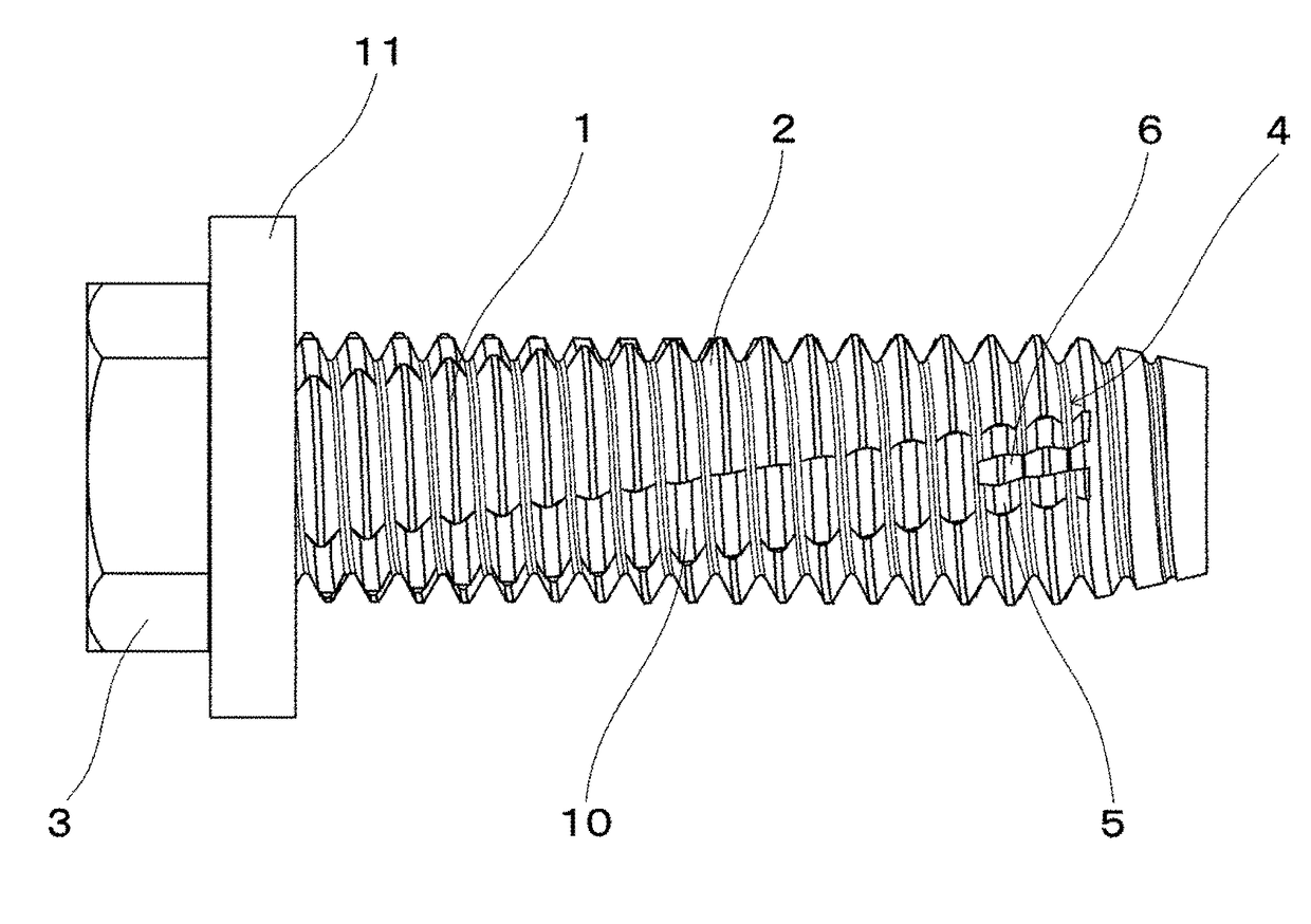
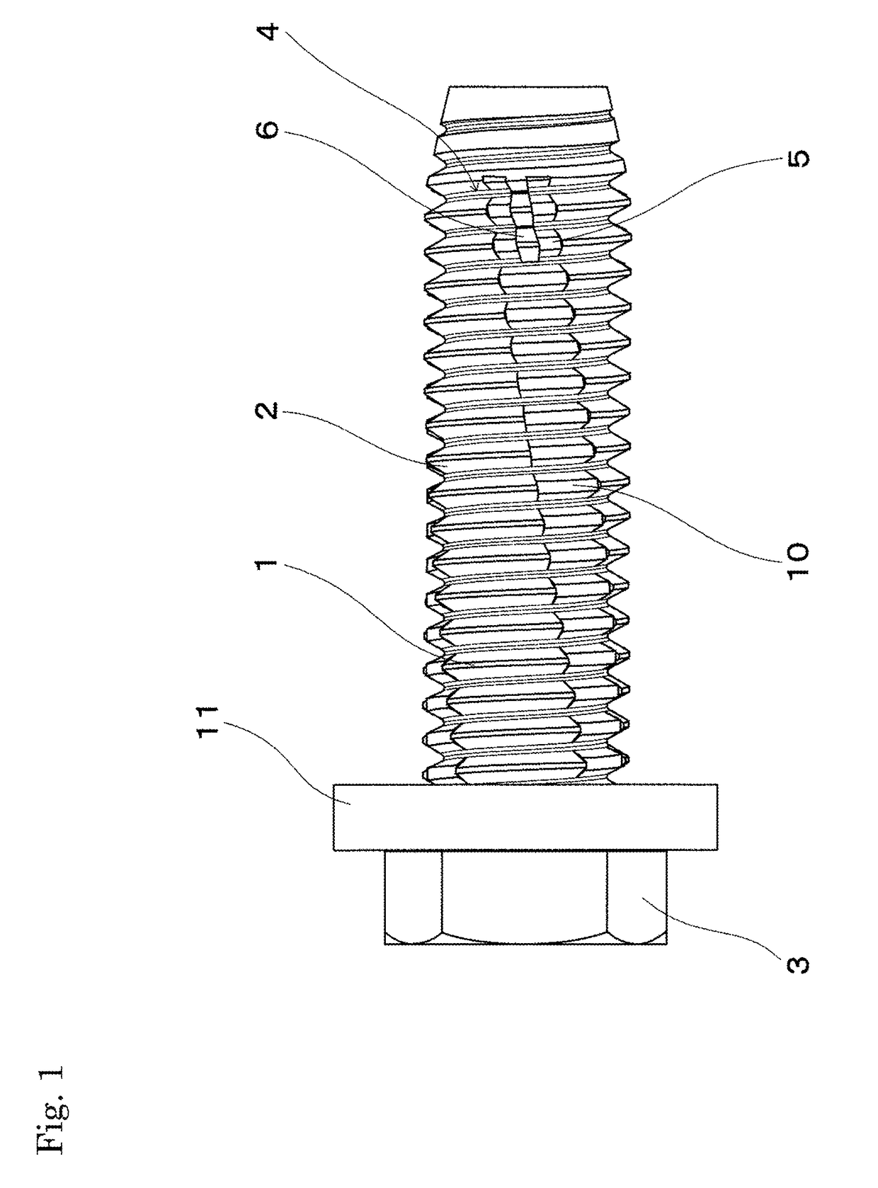
[0022]As shown in FIG. 1, the bolt of the present embodiment includes a head part 3 in an upper end part of an axis part 2 in which a regular screw part 1 is formed. The length of the axis part 2 and shape of the head part 3 are arbitrarily determined, and the shape of the head part 3 is not necessarily limited to a hexagonal head part with a flange 11 as shown. In the present embodiment, the tip end of the axis part 2 serves as a tapered guide part in which an incomplete screw is formed. However, the shape of the guide part is not necessarily limited to a guide shape as shown. Also, the guide part may be omitted.

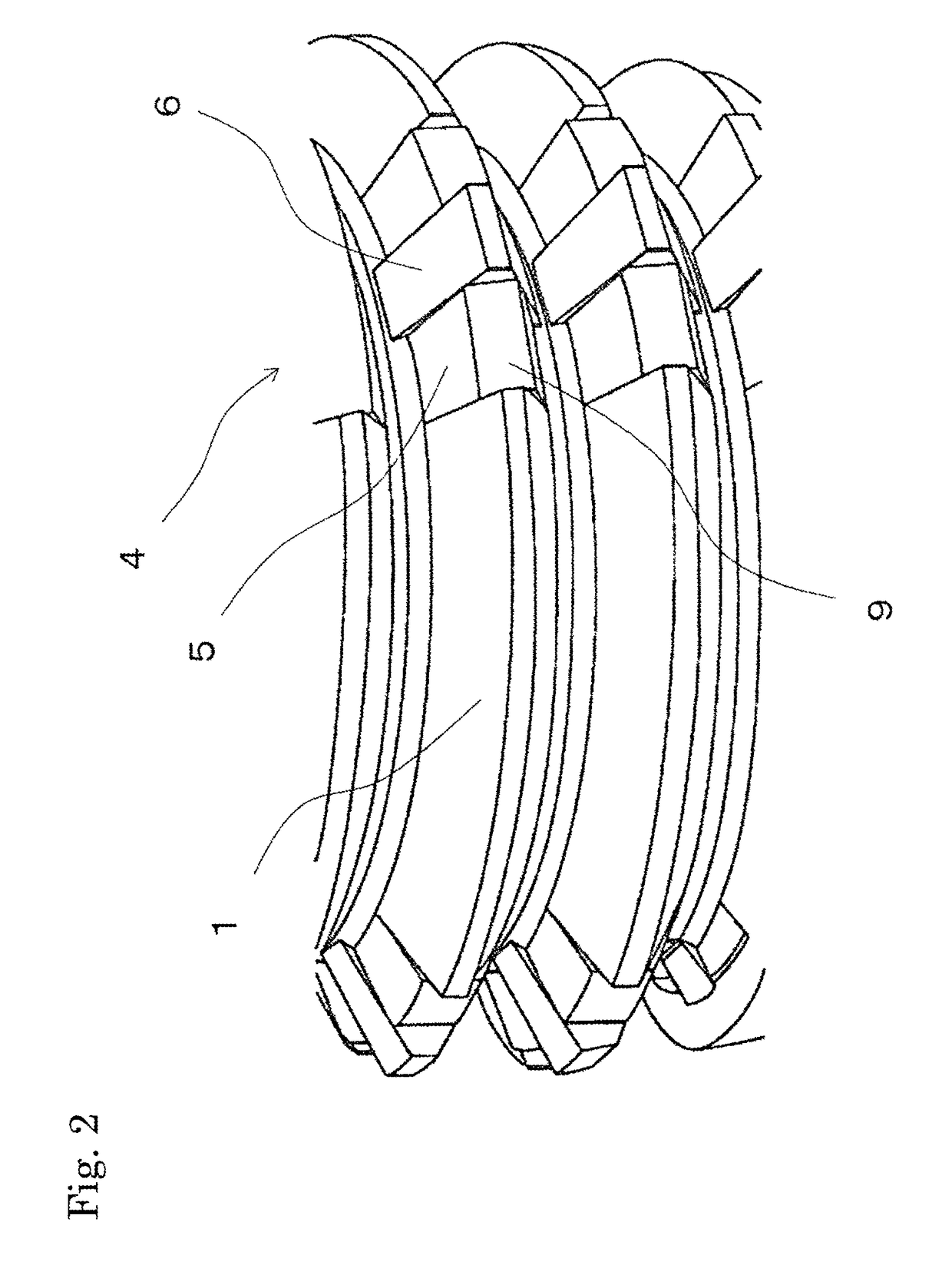
[0023]In the tip end part of this bolt, coating peeling parts 4 for peeling coating are formed at a plurality of positions in the circumferential direction. This coating peeling part 4 includes crushing parts 5 and a protruding part 6 which is formed adjacent to and between the crushing parts 5 ...


PUM


Abstract

The bolt of the present invention can reliably peel coating even when fastened with a low torque, and can secure sufficient conductivity. A coating peeling part for peeling coating is formed at a tip end of an axis part in which a regular screw part is formed. The coating peeling part includes crushing parts having a trapezoidal top part and having a flank which is projected at a different angle with respect to the flank of the regular screw part; and a protruding part which is arranged adjacent to the crushing parts and whose top part projects beyond the outer diameter of the regular screw part.

Description

BACKGROUND OF THE INVENTION[0001]Field of Invention[0002]The present invention relates to a bolt that can secure conductivity with the nut even when fastened to a nut to which coating is applied.[0003]Description of Related Art[0004]In the production lines for automobiles and the like, bolts are used to attach various parts to a body to which coating treatment is applied. Especially in the case of attachment of a part which must secure conductivity with the body, a special bolt called an earth bolt is used. This bolt includes a coating peeling part which peels coating adhered onto the inner circumferential surface of a nut, and functions to peel coating for establishing metal touch between the bolt and the nut, thereby securing conductivity.[0005]For example, Patent Literature 1 discloses an earth bolt designed in such a manner that a flank on the pressure side of a screw thread of the bolt is bent in the middle to dig the screw thread into a female screw, thereby bringing the screw...

Claims


Application Information

Patent Timeline
Patent Type & Authority Patents(United States)
IPC IPC(8): F16B35/00F16B39/30F16B25/00F16B1/00F16B35/02
CPCF16B35/007F16B25/0021F16B39/30F16B25/0052F16B2001/0064F16B2200/93
Inventor FUJIMOTO, YUKINORISHIBUYA, KAZUOKIIIDA, SATOSHIINABA, NAOKINISHIMURA, YUKIKOGA, KAZUHIRO
Owner AOYAMA SEISAKUSHO CO LTD
Why Eureka
Try Eureka