Bolt

Active Publication Date: 2016-05-19
AOYAMA SEISAKUSHO CO LTD
View PDF11 Cites 3 Cited by
  • Summary
  • Abstract
  • Description
  • Claims
  • Application Information

AI Technical Summary

Benefits of technology

The present invention provides a bolt with a coating peeling part that includes crushing parts and a protruding part. The coating peeling part allows for complete removal of coating from the screw thread of a nut, suppressing conduction failure. The screw thread design promotes plastic flow within the nut, ensuring secure peeling of the coating and high conductivity even at low torque. The protruding part is formed between the crushing parts to ensure continuous coating peeling and smooth discharge of the peeled coating film. The bolt also includes a helically formed trapezoidal locking part that can secure stable conductivity by reliably digging into the nut.

Problems solved by technology

However, the bolt of Patent Literature 1 is intended to peel coating only by a tip end part of the screw thread, and thus coating cannot completely be peeled.
Even if coating can be peeled, the peeled coating invades into a gap between the screw threads, thereby disadvantageously causing a conduction failure.
Also, the bolt of Patent Literature 2 is intended to be fastened by digging the convex part formed in the flank on the pressure side of the screw thread and having a flank angle which is approximately equal to the flank angle of the female screw, into the nut, and thus disadvantageously requires a high fastening torque in order to secure conductivity.

Method used


Image

  • Bolt
  • Bolt
  • Bolt

Examples


Embodiment Construction

[0019]Hereinafter, a preferred embodiment of the present invention is described.

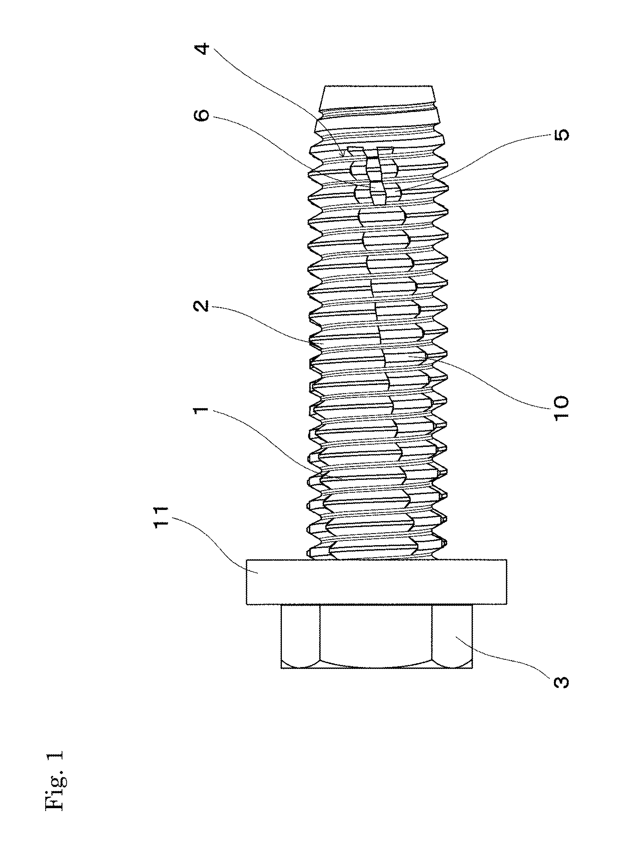
[0020]As shown in FIG. 1, the bolt of the present embodiment includes a head part 3 in an upper end part of an axis part 2 in which a regular screw part 1 is formed. The length of the axis part 2 and shape of the head part 3 are arbitrarily determined, and the shape of the head part 3 is not necessarily limited to a hexagonal head part with a flange 11 as shown. In the present embodiment, the tip end of the axis part 2 serves as a tapered guide part in which an incomplete screw is formed. However, the shape of the guide part is not necessarily limited to a guide shape as shown. Also, the guide part may be omitted.

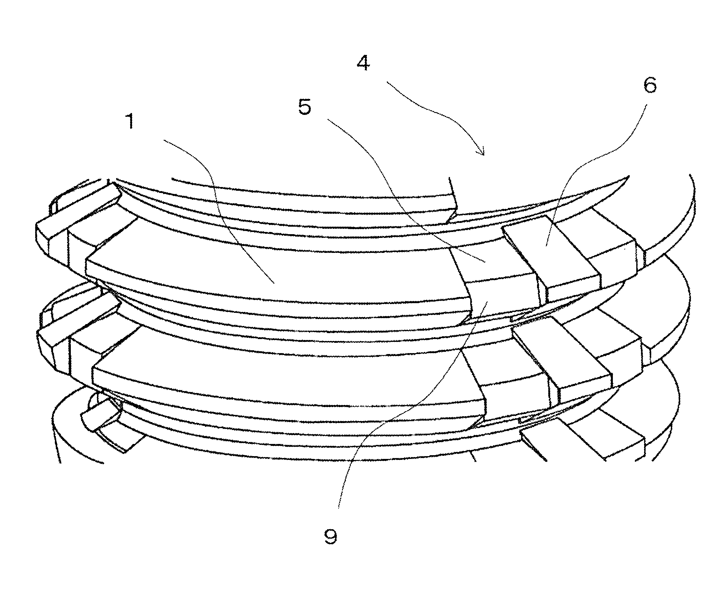
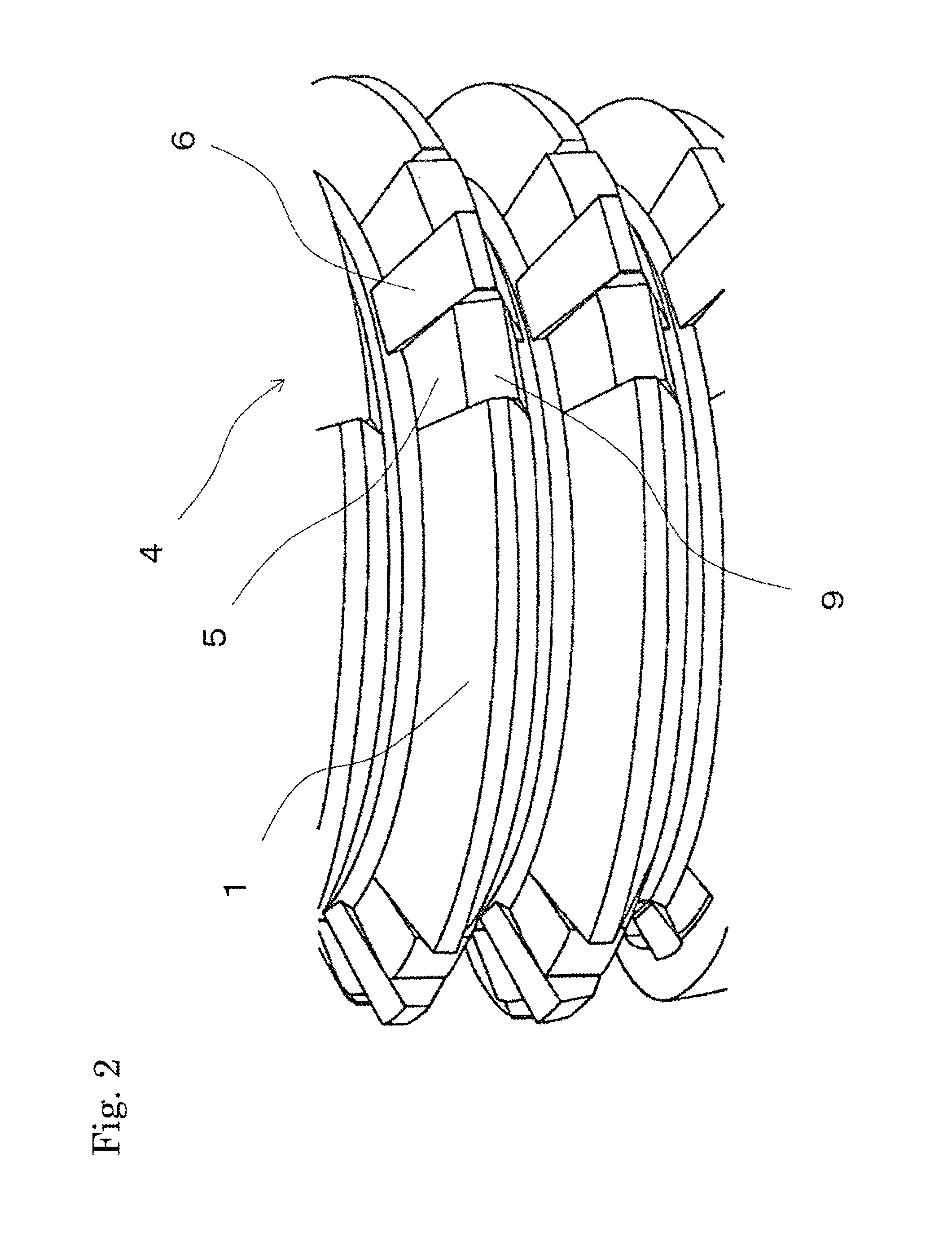
[0021]In the tip end part of this bolt, coating peeling parts 4 for peeling coating are formed at a plurality of positions in the circumferential direction. This coating peeling part 4 includes crushing parts 5 and a protruding part 6 which is formed adjacent to and between the crushing parts 5 ...


PUM


Abstract

The bolt of the present invention can reliably peel coating even when fastened with a low torque, and can secure sufficient conductivity. A coating peeling part 4 for peeling coating is formed at a tip end of an axis part 2 in which a regular screw part 1 is formed. The coating peeling part 4 includes crushing parts 5 having a trapezoidal top part and having a flank which is projected at a different angle with respect to the flank of the regular screw part 1; and a protruding part 6 which is arranged adjacent to the crushing parts 5 and whose top part projects beyond the outer diameter of the regular screw part 1.

Description

TECHNICAL FIELD[0001]The present invention relates to a bolt that can secure conductivity with the nut even when fastened to a nut to which coating is applied.BACKGROUND ART[0002]In the production lines for automobiles and the like, bolts are used to attach various parts to a body to which coating treatment is applied. Especially in the case of attachment of a part which must secure conductivity with the body, a special bolt called an earth bolt is used. This bolt includes a coating peeling part which peels coating adhered onto the inner circumferential surface of a nut, and functions to peel coating for establishing metal touch between the bolt and the nut, thereby securing conductivity.[0003]For example, Patent Literature 1 discloses an earth bolt designed in such a manner that a flank on the pressure side of a screw thread of the bolt is bent in the middle to dig the screw thread into a female screw, thereby bringing the screw threads into contact with each other. Also, Patent Li...

Claims


Application Information

Patent Timeline
IPC IPC(8): F16B35/00F16B39/30F16B25/00
CPCF16B35/007F16B39/30F16B25/0021F16B2200/93F16B25/0052
Inventor FUJIMOTO, YUKINORISHIBUYA, KAZUOKIIIDA, SATOSHIINABA, NAOKINISHIMURA, YUKIKOGA, KAZUHIRO
Owner AOYAMA SEISAKUSHO CO LTD
Why Eureka
Try Eureka