
Laminated substrate and method of manufacturing laminated substrate

a technology of laminated substrate and laminated substrate, which is applied in the direction of printed circuit manufacturing, printed circuit aspects, printed element electric connection formation, etc., can solve problems such as conduction failure, and achieve the effect of suppressing conduction failure and suppressing conduction failur

Inactive Publication Date: 2019-08-27
TOYOTA JIDOSHA KK +1
View PDF17 Cites 1 Cited by
  • Summary
  • Abstract
  • Description
  • Claims
  • Application Information

AI Technical Summary

Benefits of technology

This approach ensures that the posts maintain their connection to the wires, preventing conduction failures and allowing for the reliable manufacturing of laminated substrates with embedded electronic components while maintaining a low-cost process.

Problems solved by technology

For this reason, there may be cases where the post is not suitably connected to wires, resulting in a conduction failure.

Method used


Image

  • Laminated substrate and method of manufacturing laminated substrate
  • Laminated substrate and method of manufacturing laminated substrate
  • Laminated substrate and method of manufacturing laminated substrate

Examples


Embodiment Construction

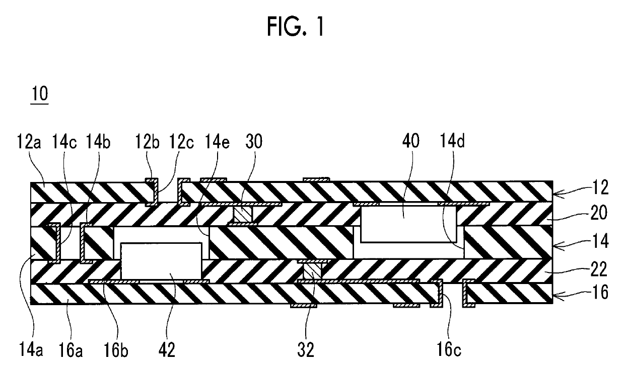
[0024]FIG. 1 shows a sectional view of a laminated substrate 10 of an embodiment. The laminated substrate 10 has a structure in which an upper substrate 12, an intermediate substrate 14, and a lower substrate 16 are laminated. Each of the upper substrate 12, the intermediate substrate 14, and the lower substrate 16 is a printed wiring board. The upper substrate 12 includes a substrate body 12a made of an insulator, and a wire 12b provided on the upper surface and the lower surface of the substrate body 12a. The wire 12b is made of copper. The wire 12b on the upper surface of the upper substrate 12 and the wire 12b on the lower surface thereof are connected by a through-hole 12c or the like. The intermediate substrate 14 includes a substrate body 14a made of an insulator, and a wire 14b provided on the upper surface and the lower surface of the substrate body 14a. The wire 14b is made of copper. The wire 14b on the upper surface of the intermediate substrate 14 and the wire 14b on th...


PUM

PropertyMeasurementUnit
melting pointaaaaaaaaaa
particle sizeaaaaaaaaaa

Abstract

A laminated substrate includes: a first substrate; a second substrate having a through-hole; a third substrate; a first adhesive layer bonding a rear surface of the first substrate and a front surface of the second substrate; a second adhesive layer bonding a rear surface of the second substrate and a front surface of the third substrate; a first post penetrating through the first adhesive layer, electrically connecting the first substrate to the second substrate, and made of an alloy of a high melting point metal and a low melting point metal; a second post penetrating through the second adhesive layer, electrically connecting the second substrate to the third substrate, and made of an alloy of the high melting point metal and the low melting point metal; and an electronic component fixed to the front surface of the third substrate and disposed in the through-hole of the second substrate.

Description

INCORPORATION BY REFERENCE[0001]The disclosure of Japanese Patent Application No. 2017-194304 filed on Oct. 4, 2017 including the specification, drawings and abstract is incorporated herein by reference in its entirety.BACKGROUND1. Technical Field[0002]The disclosure relates to a laminated substrate and a method of manufacturing a laminated substrate.2. Description of Related Art[0003]Japanese Unexamined Patent Application Publication No. 2012-248897 (JP 2012-248897 A) discloses a laminated substrate. The laminated substrate includes a structure having a plurality of substrates laminated. Electronic components are embedded in the laminated substrate. The substrates (more specifically, wires of the substrates) in the laminated substrate are electrically connected to each other by an interlayer connector (hereinafter, referred to as a post in the disclosure).[0004]Japanese Unexamined Patent Application Publication No. 6-342977 (JP 6-342977 A) discloses a technique for forming a post o...

Claims


Application Information

Patent Timeline
Patent Type & Authority Patents(United States)
IPC IPC(8): H05K1/02H05K3/40H05K3/46H05K1/11H05K1/09
CPCH05K1/11H05K3/4614H05K1/186H05K2201/0305H05K2203/063H05K3/4069H05K1/0298H05K1/115H05K3/4652H05K1/095H05K3/4647
Inventor GOTO, AKIHITOSAKATA, MASAHIROYAMAGUCHI, MASAKI
Owner TOYOTA JIDOSHA KK
Learn More