High dynamic range ion detector for mass spectrometers

a mass spectrometer and dynamic measurement technology, applied in the direction of electron/ion optical arrangement, particle separator tube details, electron/ion sources, etc., can solve the problem that the dynamic range of the digitizer is insufficient for the analytic task, the mcp cannot maintain a gain of 1000 electrons, and the linear dynamic measurement range of the amplifying and digitizing device is limited, so as to achieve high transmission factor and high open area ratio. the effect of high aspect ratio ratio ratio ratio ratio ratio ratio ratio ratio ratio ratio ratio ratio ratio ratio ratio ratio ratio ratio ratio ratio ratio ratio ratio ratio ratio ratio ratio ratio ratio ratio ratio ratio ratio ratio ratio

Active Publication Date: 2018-02-20
BRUKER SCI LLC
View PDF23 Cites 19 Cited by
  • Summary
  • Abstract
  • Description
  • Claims
  • Application Information

AI Technical Summary

Benefits of technology

[0019]The grid-like detection element used for the image current measurements preferably has a high transmission factor, favorably in the order of 90 percent or higher. The grid may be made from thin wires. Alternatively, a preferred version of the detection element consists of a thin conducting plate having a high open area ratio—the open area consisting of holes having high aspect ratios. The high open area ratio allows for high electron transmission efficiency, preferably 90% or greater. The aspect ratio of the holes—the depth of the holes divided by their diameter—is preferably such that at some point during the transit of ele

Problems solved by technology

All these types of secondary electron multiplier have good characteristics for quantitative measurements of the ion current; however, in some applications either the linear dynamic range of the SEM, the linear dynamic range of the amplifier, or the linear dynamic range of the digitizer is insufficient for the analytic task.
Using chevron MCP as secondary electron multiplier, at high ion intensities the number of secondary electrons collected at the anode is no longer proportional to the number of ions striking the detector because the secon

Method used


Image

  • High dynamic range ion detector for mass spectrometers
  • High dynamic range ion detector for mass spectrometers
  • High dynamic range ion detector for mass spectrometers

Examples


Embodiment Construction

[0027]While the invention has been shown and described with reference to a number of different embodiments thereof, it will be recognized by those of skill in the art that various changes in form and detail may be made herein without departing from the scope of the invention as defined by the appended claims.

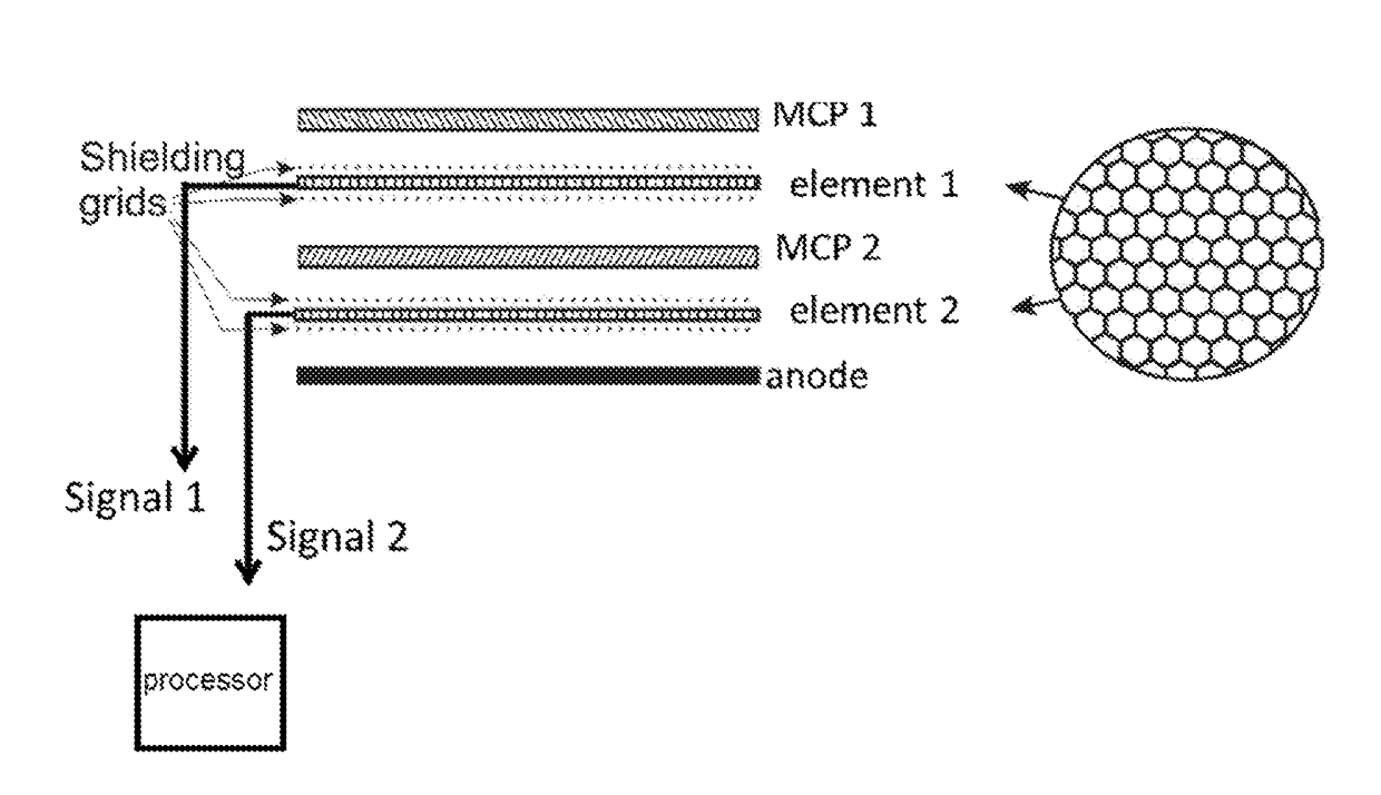
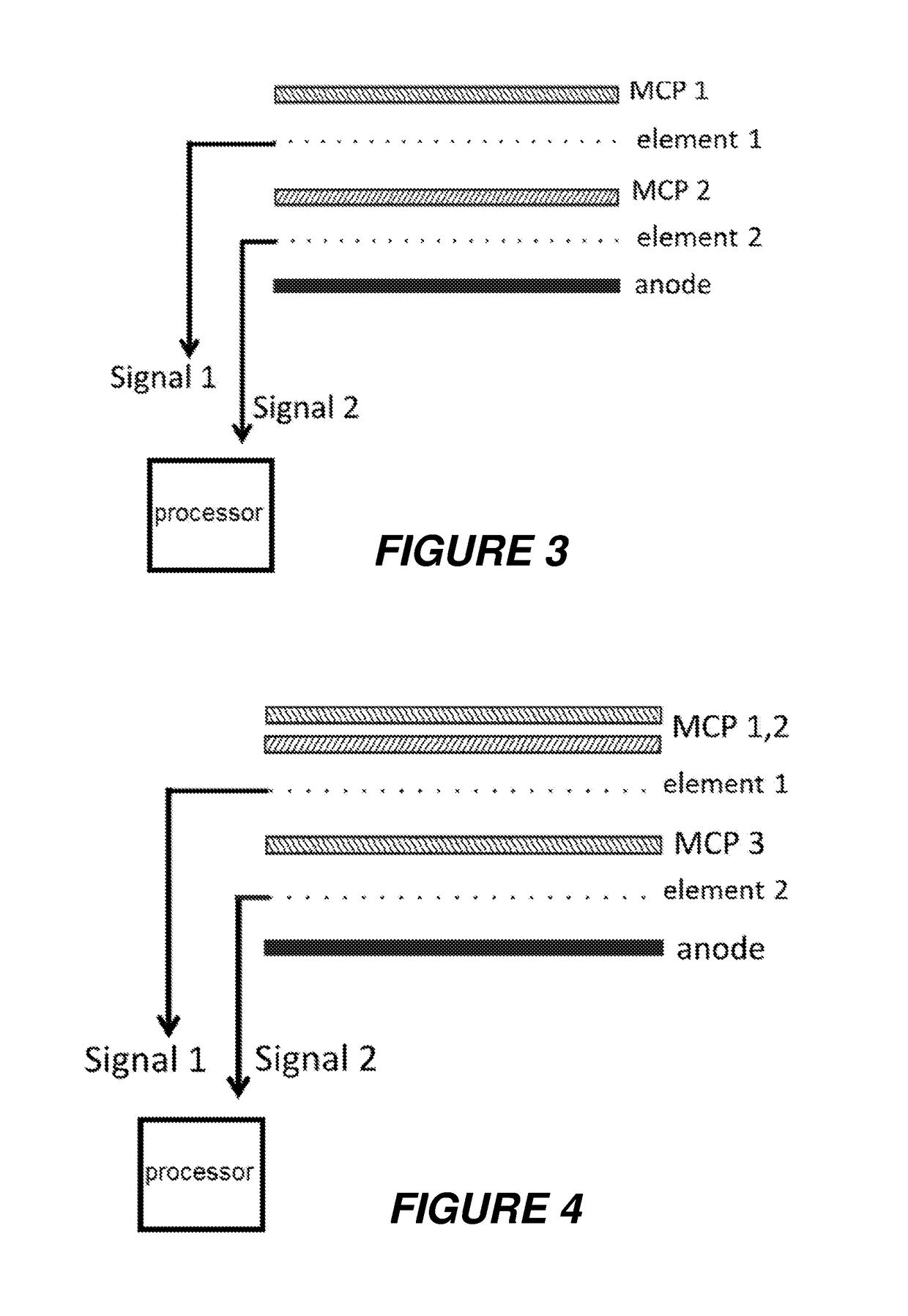
[0028]In FIG. 3, two grid-like detection elements are placed before and after the second MCP 2 of an arrangement that would normally be used in an MCP detector. The detection elements may, for example, be configured for 90% transmission so that 90% of the electrons from the first MCP pass through detection element 1 and strike MCP 2 for further amplification. The electrons produce in detection element 1 an image current called “signal 1”. Electrons from MCP 2 pass through detection element 2 and produce an image current called “signal 2”. (See, for instance, M. A. Park and J. H. Callahan, Rapid Com. Mass Spectrom. 8 (4), 317, 1994). The passing electrons are neutralized at the a...


PUM


Abstract

The invention relates to the linear dynamic range of ion abundance measurement devices in mass spectrometers, such as time-of-flight mass spectrometers. The invention solves the problem of ion current peak saturation by producing a second ion measurement signal at an intermediate stage of amplification in a secondary electron multiplier, e.g. a signal generated between the two multichannel plates in chevron arrangement. Because saturation effects are observed only in later stages of amplification, the signal from the intermediate stage of amplification will remain linear even at high ion intensities and will remain outside saturation. In the case of a discrete dynode detector this could encompass, for example, placement of a detection grid between two dynodes near the middle of the amplification chain. The invention uses detection of the image current generated by the passing electrons.

Description

BACKGROUND OF THE INVENTIONField of the Invention[0001]This invention relates to the dynamic range of ion abundance measurement devices in mass spectrometers.Description of the Related Art[0002]There are in principle two main types of mass spectrometers: In a first type, ions are excited to circulations or oscillations with mass-dependent frequencies in magnetic or electric fields, the frequencies are measured by image currents induced in suitable electrodes, and Fourier transformations are used to transform ion current transients into frequency values which can be scaled to mass values. This first type mainly comprises ion cyclotron resonance mass spectrometers (ICR-MS) and Kingdon mass spectrometers, e.g. the Orbitrap® (Thermo-Fisher Scientific).[0003]In a second type of mass spectrometer, the ions of an ion current from an ion source are directly separated by their masses in time or space, using some kind of “scan”; a measurement of the mass-separated ion current with high tempor...

Claims


Application Information

Patent Timeline
IPC IPC(8): H01J49/40H01J49/02H01J49/08H01J49/06
CPCH01J49/08H01J49/40H01J49/025H01J43/246H01J49/027
Inventor PARK, MELVIN ANDREW
Owner BRUKER SCI LLC
Why Eureka
Try Eureka