
Control device for vehicle drive device

a control device and driving device technology, applied in mechanical equipment, propulsion parts, transportation and packaging, etc., can solve the problems of large amount of heat generated, reduce energy efficiency, and the kinetic energy during the shifting cannot be collected, so as to achieve reliable and easy determination

Active Publication Date: 2017-11-14
AISIN AW CO LTD
View PDF14 Cites 2 Cited by
  • Summary
  • Abstract
  • Description
  • Claims
  • Application Information

AI Technical Summary

Benefits of technology

The patent describes a solution to a problem in shifting in vehicles. In traditional shifts, there is a lot of heat generated during the process. This is especially true for jumping shifts, which are shifts where the shift speed is changed by a large amount and for a longer time. The patent proposes a solution that reduces the difference in shift speed between the current and the target shift speed, making it easier to determine which shifts can be safely performed. This solution helps to prevent heat damage and reduces the wear and tear on vehicle components.

Problems solved by technology

Accordingly, kinetic energy during the shifting cannot be collected, which reduces energy efficiency.
A large amount of heat is therefore generated during the slip engagement.
Moreover, in the case of a jumping shift, the amount of heat generation of the engagement element is increased due to a large difference between the rotational speed of an input shaft of an automatic transmission before shifting and that after the shifting, and a longer shift time as compared to a normal downshift.
As described above, if the time required for the jumping shift is longer than the predetermined limit shift time, the control device does not permit the computed jumping shift.

Method used


Image

  • Control device for vehicle drive device
  • Control device for vehicle drive device
  • Control device for vehicle drive device

Examples


first embodiment

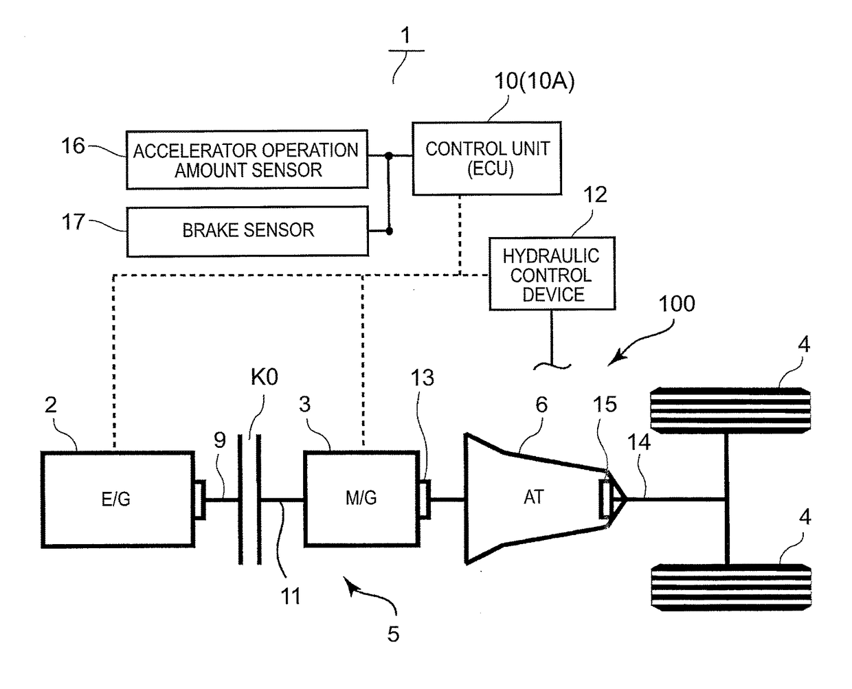
[0099]Accordingly, in the present embodiment, whether a jumping shift can be performed or not is determined based also on the requirement for the estimated temperature of the friction engagement element during shifting in view of the current temperature of the active friction engagement element, in addition to the requirements for the amount of heat generation and the control time in the That is, as shown in FIG. 11, a control unit 10A according to the present embodiment functions as a current temperature calculating unit 40, and constantly calculates and estimates the current temperature of the active friction engagement element based on the heat balance (the sum of heat input and heat dissipation to and from the active friction engagement element, and the ATF temperature) accumulated up until a shift is performed.

[0100]Once the amount of heat generation of the active friction engagement element is calculated for shifting, the control unit 10A functions as an estimated temperature...

second embodiment

[0104]In the second embodiment, whether a jumping shift can be performed or not is determined based on all of the requirement liter the amount of heat generation, the requirement for the estimated temperature, and the requirement for the shift time. However, whether a jumping shift can be performed or not can be determined based only on, e.g., the requirement for the amount of heat generation. Alternatively, whether a jumping shift can be performed or not can be determined based only on the requirement for the estimated temperature, or whether a jumping shift can be performed or not can be determined based only on the requirement for the amount of heat generation and the requirement for the estimated temperature.

[0105]In the first to third embodiments, a hybrid drive device is described as an example of the vehicle drive device. However, an engine is not necessarily required as a driving source, and the present embodiment is applicable to any vehicle drive device that includes a rot...


PUM


Abstract

A control device for a vehicle drive device having a speed change mechanism that attains a predetermined shift speed by engaging multiple engagement elements. The control device predicts an amount of heat generation and determines whether any jumping shift from the current shift speed to the shift speed that is the multiple shift speeds higher or lower than the current shift speed can be permitted or not between the current shift speed and the target shift speed, and if the jumping shift can be permitted, the control unit performs the jumping shift and controls the speed change mechanism so as to shift the shift speed from the current shift speed to the target shift speed.

Description

TECHNICAL FIELD[0001]Preferred embodiments relate to control devices for vehicle control devices in which a rotating electrical machine is provided on the input side of a speed change mechanism.BACKGROUND ART[0002]In recent years, as represented by, e.g., vehicles such as hybrid vehicles and electric vehicles, vehicles have been increasingly developed which include a rotating electrical machine as a driving source and have energy efficiency enhanced by converting kinetic energy of the vehicle to electrical energy and collecting the electrical energy by regeneration of the rotating electrical machine.[0003]For example, Japanese Patent Application Publication No. 2008-94253 (JP 2008-94253 A) describes a hybrid vehicle having a rotating electrical machine (motor generator) provided between an engine and a stepped automatic transmission, in which a jumping downshift of the stepped automatic transmission is performed to cause regeneration of the rotating electrical machine at a high rota...

Claims


Application Information

Patent Timeline
Patent Type & Authority Patents(United States)
IPC IPC(8): B60W20/00B60W20/14B60W20/11F16H59/72B60W30/186B60W20/30F16H61/16F16H61/21B60K6/48B60W10/115
CPCB60W20/30B60W20/11B60W20/14B60W30/186F16H59/72F16H61/16Y10S903/945B60W10/115B60W2710/1005F16H61/21F16H2059/725F16H2306/14Y02T10/6252B60K2006/4825Y02T10/62
Inventor TSUDA, KOHEIONOUCHI, TOMOHIROKUSABE, KEIICHIROU
Owner AISIN AW CO LTD
Learn More