
Method and system for rapid construction of structurally reinforced concrete structures using prefabricated assemblies and method of making the same

a technology of structural reinforcement and prefabricated assemblies, which is applied in the direction of structural elements, building components, constructions, etc., can solve the problems of burden on low skill labor on construction sites, burden on low skill labor, and component manufacturing in a factory oftentimes to higher levels of complexity, so as to minimize logistical burden and cost, and high quality construction

Active Publication Date: 2017-06-20
KT INDIA
View PDF15 Cites 24 Cited by
  • Summary
  • Abstract
  • Description
  • Claims
  • Application Information

AI Technical Summary

Benefits of technology

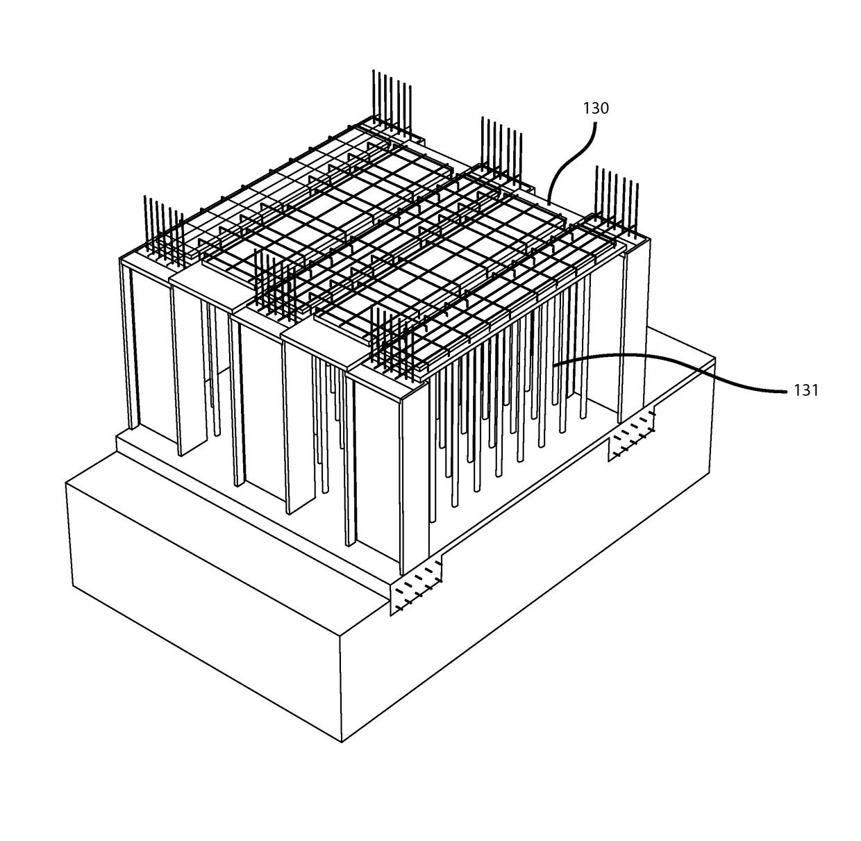
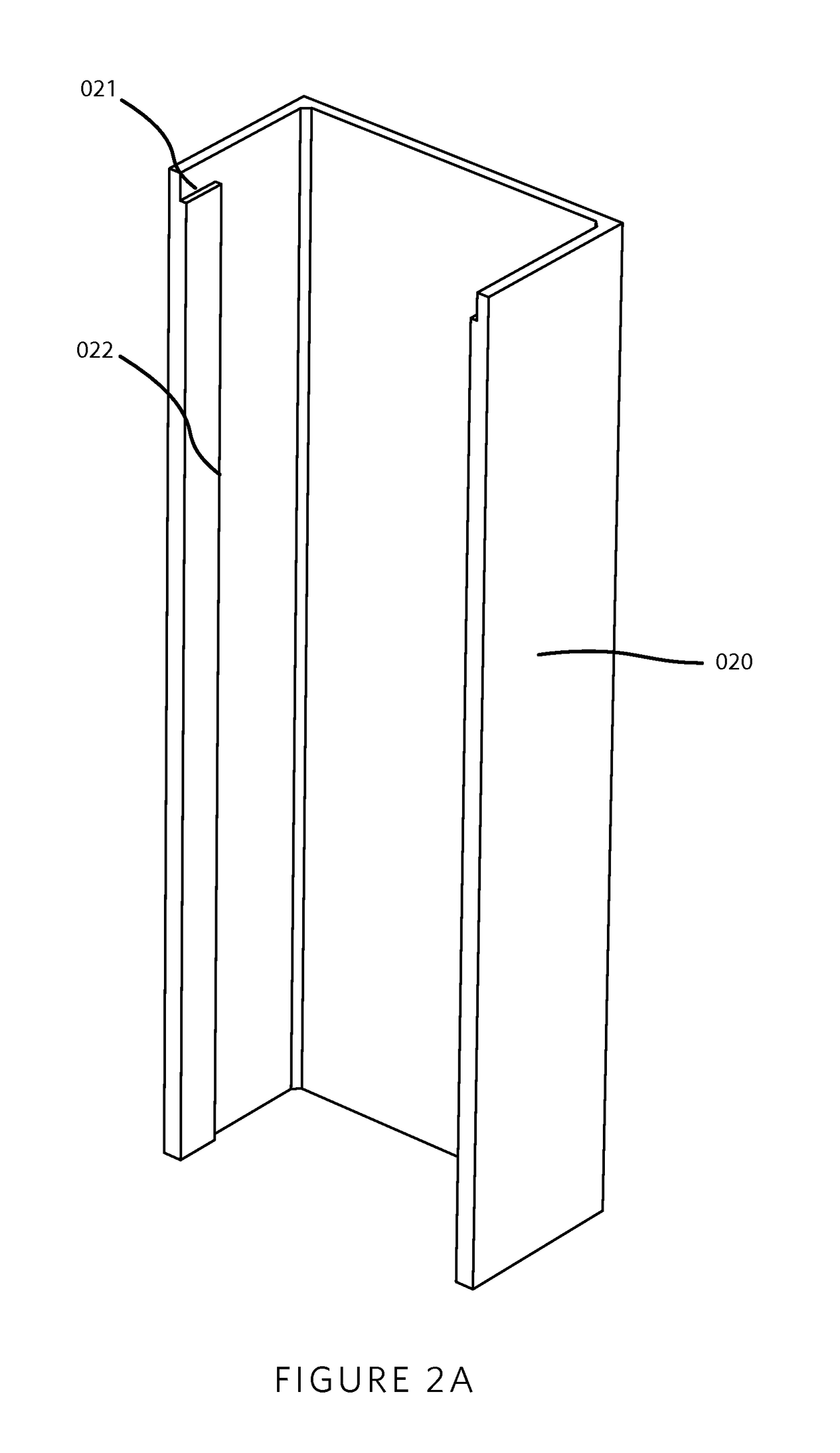
The invention provides a construction method using prefabricated assembly components to form a permanent concrete mold on a construction site, which can then be cast in place to create a cast in place concrete structure. The prefabricated assembly components include a column form assembly, a column closure panel assembly, a beam form assembly, and a slab form assembly. The shaped form of the assembly components is made of concrete, fiber reinforced plastic, or molded plastic, and may include keying geometries to prevent improper assembly. The integrated structural reinforcement may include steel bars, steel wire, carbon fiber reinforced composite bars, glass fiber reinforced composite bars, aramid fiber reinforced composite bars, bamboo, or perforated steel sheet. The prefabricated assembly components can be assembled on a construction site to create a permanent concrete structure.

Problems solved by technology

These components are manufactured in a factory oftentimes to higher levels of complexity than what is achievable in the field.
First, cast in place reinforced concrete requires the manipulation of formwork and mold components, which can be burdensome and complex for low skill labor on construction sites.
Manipulating this formwork on site also entails proper placement of structural reinforcement, which again is a burden to low skill labor.
Some notable examples of structural failure familiar to those skilled in the art include cases in which on site labor neglected to include structural reinforcement, leading to catastrophic failure.
Further, the designer has little control over the quality of the concrete available on site, particularly with regard to construction sites in developing countries.
Conventional cast in place concrete structures result in a surface finish which is dependent on the quality of the concrete on site, the surface finish and condition of the formwork, and the skill of the on-site labor, which again limits the quality attainable by conventional cast in place concrete.
Material handling equipment typically used to place large or heavy precast components can be limited to various construction site logistics, so it is often in the interest of the designer to minimize the size or weight of a precast component to facilitate construction.
Designs which are limited in the size or weight of a precast component are typically cast in place instead; however, cast in place constructions are limited in the manner discussed previously.
The need to construct concrete structures in certain developing countries is significantly complicated by the lack of available skilled labor and on site quality control measures such as inspections and testing.
Assembling such conventional precast concrete structures and ensuring the quality of integral connections is burdensome for low skill labor; for example, torque control fastening may not be available on site, a construction site may lack workers with the required training for installing or welding structural connections, a construction site may lack the requisite inspection capacity required for structural connections, or the proper steel finishing techniques for the structural connections may not be accessible in such developing countries.

Method used


Image

  • Method and system for rapid construction of structurally reinforced concrete structures using prefabricated assemblies and method of making the same
  • Method and system for rapid construction of structurally reinforced concrete structures using prefabricated assemblies and method of making the same
  • Method and system for rapid construction of structurally reinforced concrete structures using prefabricated assemblies and method of making the same

Examples


Embodiment Construction

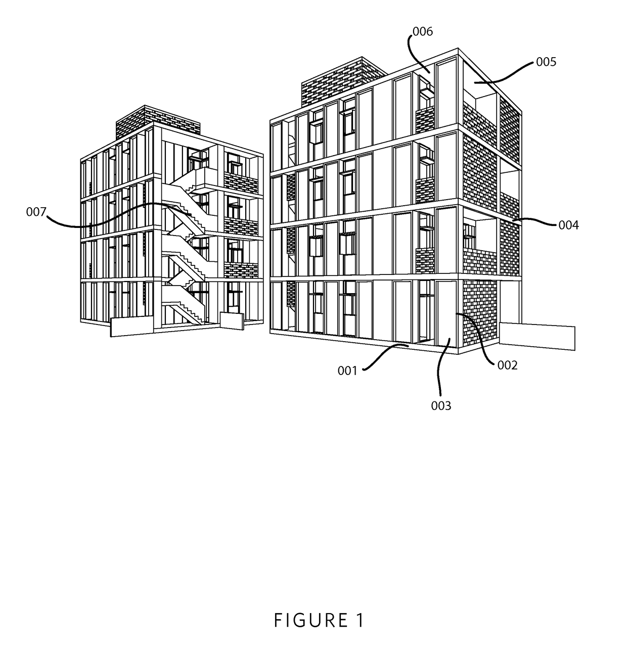
[0051]The present invention is typically applied to the construction of single story and multi-story buildings, such as single-family houses, multi-family residences, commercial properties, and other buildings in which humans can reside, work, gather or the like. Thus, the expression “prefabricated assembly component” as used herein refers to structural elements of such buildings and as such, does not encompass building blocks or structural components for toys and miniature models. FIG. 1 depicts non-limiting examples of buildings, which utilize the present invention. Each building features a 001 slab on grade formed of steel reinforced concrete, which is familiar to those skilled in the art. The typical building is structured of features which are formed from assemblies and methods related to the present invention, such as structural columns 002, 003, structural beams 004, 005, slabs 006 and staircases 007. In addition, other precast structures unrelated to the present invention ar...


PUM

PropertyMeasurementUnit
densityaaaaaaaaaa
lengthaaaaaaaaaa
timeaaaaaaaaaa

Abstract

The present invention includes prefabricated assemblies which are assembled on a construction site to provide a permanent concrete mold with integrated structural reinforcement and structural splices for cast-in-place concrete structures. The invention enhances the quality of the cast concrete structure while lowering the cost of construction and construction time. Described herein is a column form assembly, a column closure panel assembly, a beam form assembly, and a slab form assembly which are used to construct cast in place structurally reinforced concrete columns, beams, and floor slabs with minimal form work and construction site logistics. Also described herein are a method of assembly of said structures and a method of fabricating said assemblies.

Description

CROSS-REFERENCE TO RELATED APPLICATIONS[0001]This PCT application claims the benefit under 35 U.S.C. §119(e) of Provisional Patent Application Ser. No. 61 / 820,969 filed on May 8, 2013 entitled METHOD AND SYSTEM FOR RAPID CONSTRUCTION OF STRUCTURALLY REINFORCED CONCRETE STRUCTURES USING PREFABRICATED ASSEMBLIES AND METHOD OF MAKING THE SAME and whose entire disclosure is incorporated by reference herein.[0002]The claimed invention was made by, on behalf of, and / or in connection with the following parties to a joint research agreement: KT-India LLC and CVM Engineers. The joint research agreement was in effect on or before the date the claimed invention was made, and the claimed invention was made as a result of activities undertaken within the scope of the joint research agreement.BACKGROUND OF THE INVENTION[0003]1. Field of Invention[0004]This invention relates to precast concrete components of structures and prefabricated structural reinforcement of cast in place concrete structures...

Claims


Application Information

Patent Timeline
Patent Type & Authority Patents(United States)
IPC IPC(8): E04B1/04E04C2/22E04C2/06E04B5/36E04B5/38E04C5/06E04B1/16
CPCE04B1/167E04B1/161E04B1/165E04B5/36E04B5/38E04C2/06E04C2/22E04C5/0604
Inventor TIMBERLAKE, JAMESFAIRCLOTH, BILLIEMEDLIN, TAYLORSCHAEFFER, ROBMORRISON, JONMACNEAL, CHRISCURRY, PETER
Owner KT INDIA
Learn More