Composite rolling mill roll and rolling method
a composite rolling mill and rolling method technology, applied in metal rolling, metal rolling arrangement, manufacturing tools, etc., can solve the problems of increasing the roughness of the surface of the roll, reducing the strength of cracking in the outer layer of the roll, so as to improve the resistance to deterioration of the roll surface, increase the life of the composite rolling mill roll, and improve the effect of cracking resistan
- Summary
- Abstract
- Description
- Claims
- Application Information
AI Technical Summary
Benefits of technology
Problems solved by technology
Method used
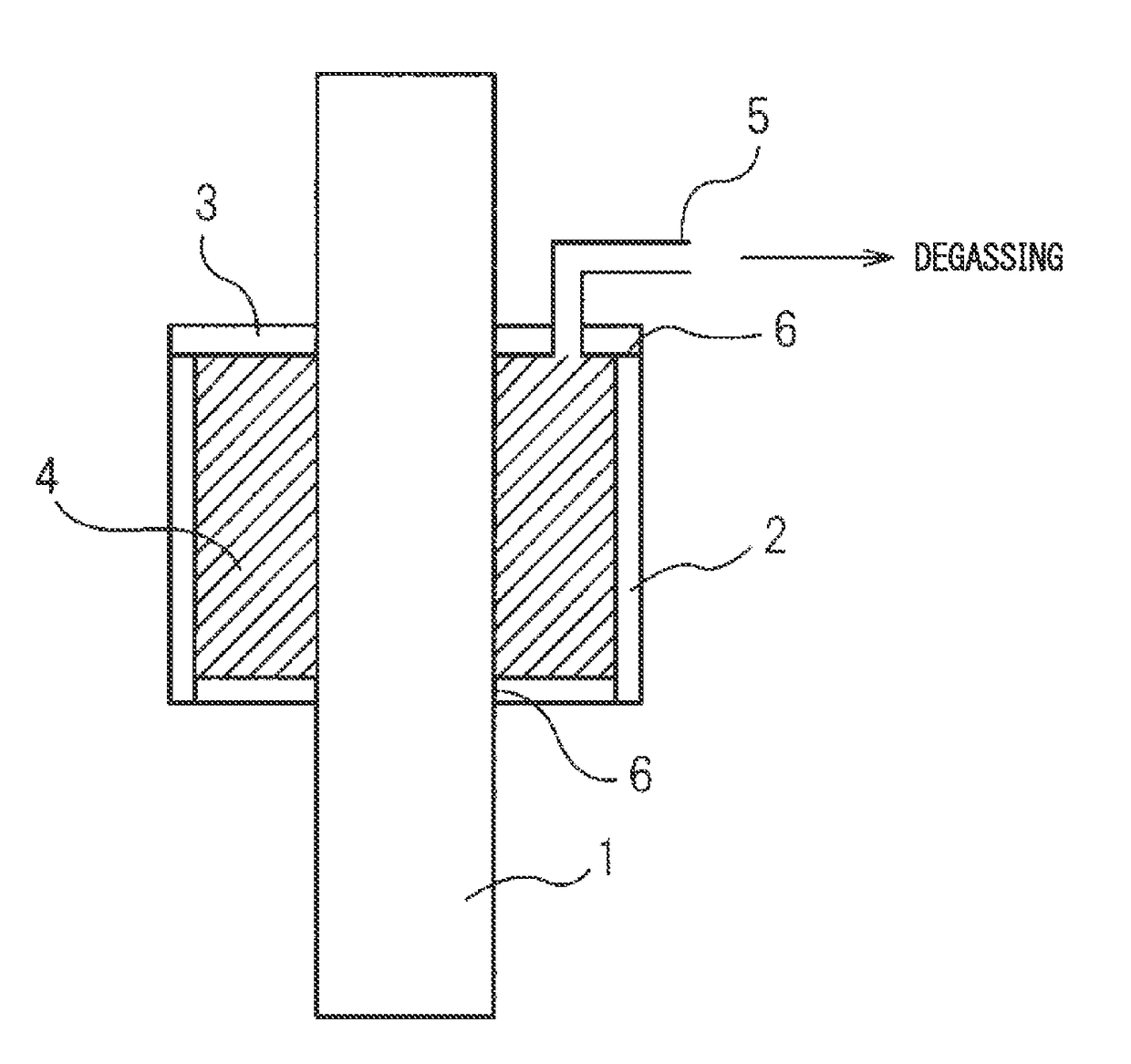
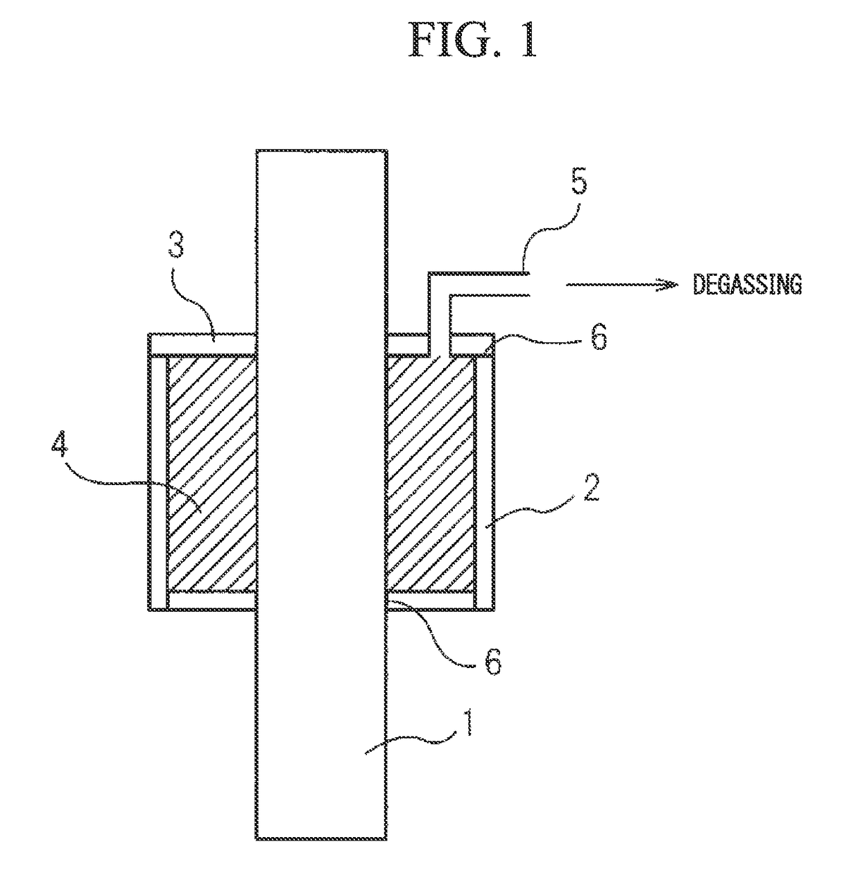
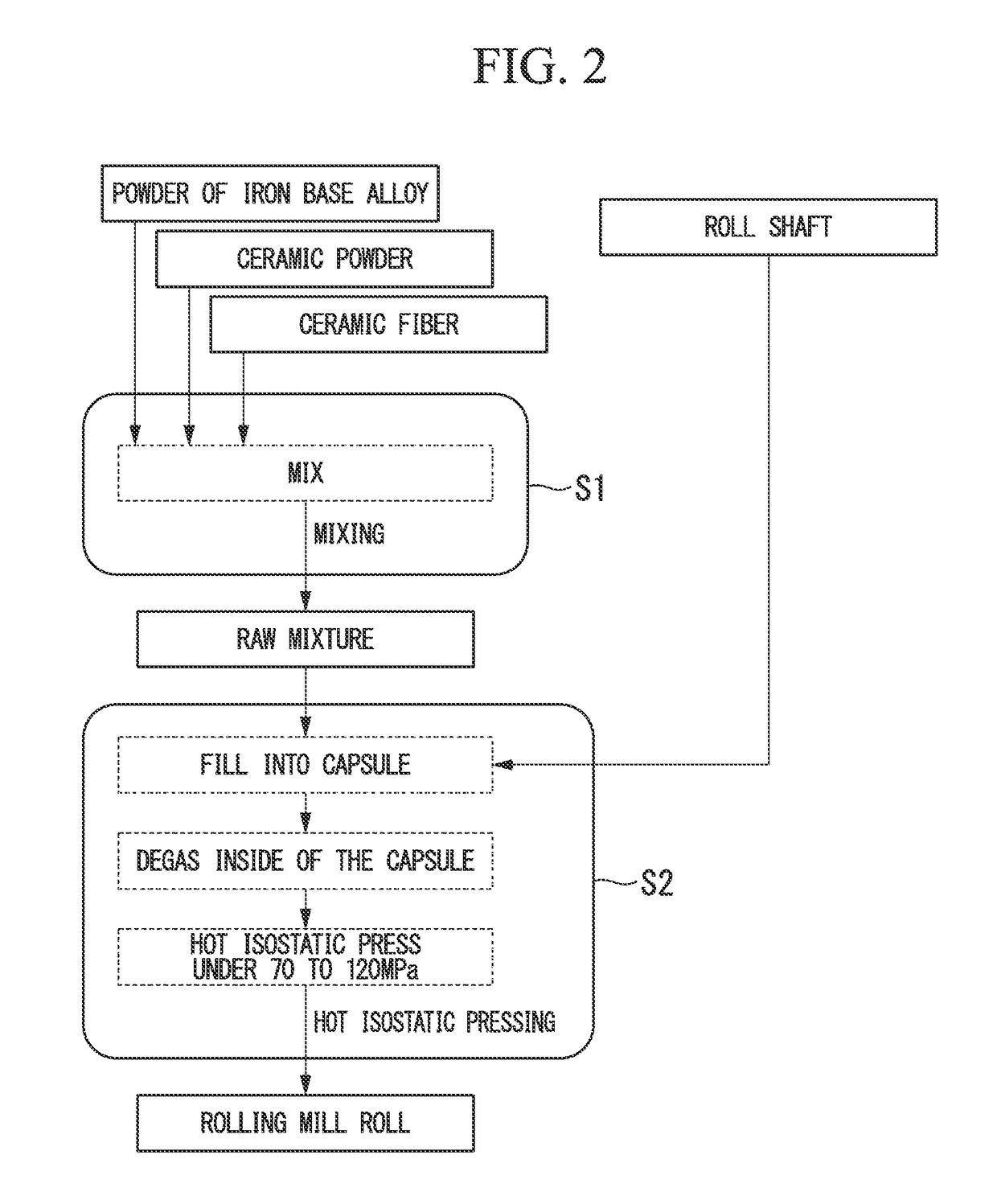
Image

Examples
examples
[0074]Using raw materials and methods described below, various composite rolling mill rolls according to Examples and Comparative Examples were prepared, and properties thereof were evaluated.
(Used Raw Materials)
[0075]As the powder of the iron alloy, a powder including 2.1 wt % of C, 4.8 wt % of Cr, 6.0 wt % of V, 5.1 wt % of Mo, 4.5 wt % of W, 1.3 wt % of Si, 0.9 wt % of Mn, and a remainder substantially including Fe an impurity was used. As the average diameter of the powder of the iron alloy, several diameter were selected and used in a range of 0.5 to 125 μm. As the ceramic powder, an alumina powder, a SiC powder, a B4C powder, and a silicon nitride powder whose average diameter were selected in a range of 0.7 to 125 μm were used. As the ceramic fiber, an alumina fiber (average diameter: 0.8 to 3.6 μm, average aspect ratio: about 8 to 603), a silicon nitride fiber (average diameter: 10 μm, average aspect ratio: 105), a SiC fiber (average diameter: 8 μm, average aspect ratio: 89)...
PUM
| Property | Measurement | Unit |
|---|---|---|
| diameter | aaaaa | aaaaa |
| diameter | aaaaa | aaaaa |
| aspect ratio | aaaaa | aaaaa |
Abstract
Description
Claims
Application Information
 - R&D
- Intellectual Property
- Life Sciences
- Materials
- Tech Scout
- Unparalleled Data Quality
- Higher Quality Content
- 60% Fewer Hallucinations
Browse by: Latest US Patents, China's latest patents, Technical Efficacy Thesaurus, Application Domain, Technology Topic, Popular Technical Reports.
© 2025 PatSnap. All rights reserved.Legal|Privacy policy|Modern Slavery Act Transparency Statement|Sitemap|About US| Contact US: help@patsnap.com