
Broadband emission material and white light emission material

a technology of emission material and white light, applied in the direction of active medium material, sustainable building, instruments, etc., can solve the problems of insufficient cyan component light (up to 500 nm) and red component light (600 nm or more), and it is difficult for white light emitting devices to achieve high color rendering properties. , to achieve the effect of higher emission intensity

Active Publication Date: 2017-05-30
CENT GLASS CO LTD
View PDF55 Cites 1 Cited by
  • Summary
  • Abstract
  • Description
  • Claims
  • Application Information

AI Technical Summary

Benefits of technology

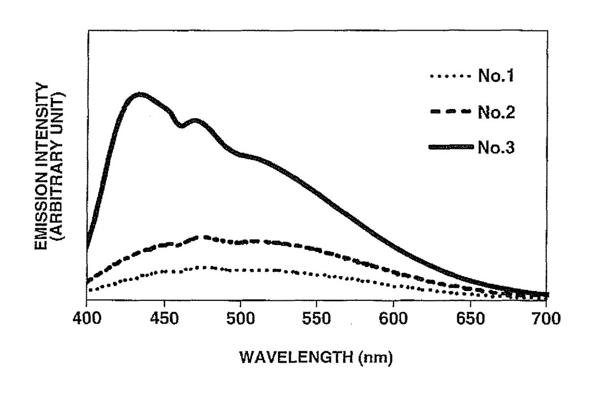
The present invention relates to a new fluoride glass composition that can be used as a white light emission material with high color-rendering properties. By adding a halide except fluoride to the fluoride glass, the emission intensity of Yb2+ over a broad band is increased. Additionally, by decreasing the barium content of the fluoride glass, it can be used as a white light emission material even without the addition of a phosphor. This new emission material can be utilized for a high-color-rendering white light source with enhanced emission intensity.

Problems solved by technology

However, the conventional combination of YAG-Ce yellow phosphors and blue LEDs faces the problem that cyan component light (up to 500 nm) and red component light (600 nm or more) are not sufficient.
Even when the white light emitting devices are each produced with a plurality of phosphors, it is difficult for the white light emitting devices to achieve high color-rendering properties due to very low emission intensity at wavelengths midway between the center emission wavelengths of the respective phosphors.
The conventional combination of YAG-Ce yellow phosphors and blue LEDs also has the problem that the use of a part of blue excitation light as illumination light leads to variations in the color of the illumination light depending on the thickness of the phosphor layer through which the blue light passes (Patent Document 3) even though it is advantageous in terms of a small strokes shift and high emission efficiency by a small difference between excitation wavelength (about 450 nm) and fluorescence wavelength (center wavelength: about 550 nm; wavelength shift depending on the amounts of Gd and Y added).

Method used


Image

  • Broadband emission material and white light emission material
  • Broadband emission material and white light emission material
  • Broadband emission material and white light emission material

Examples


example 1

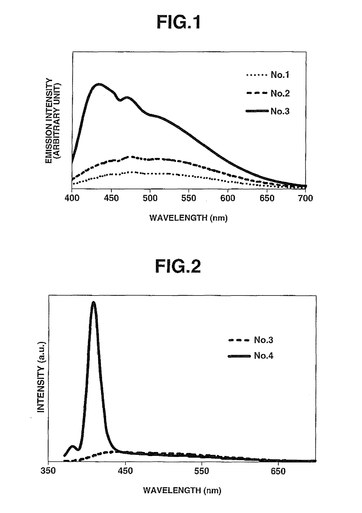
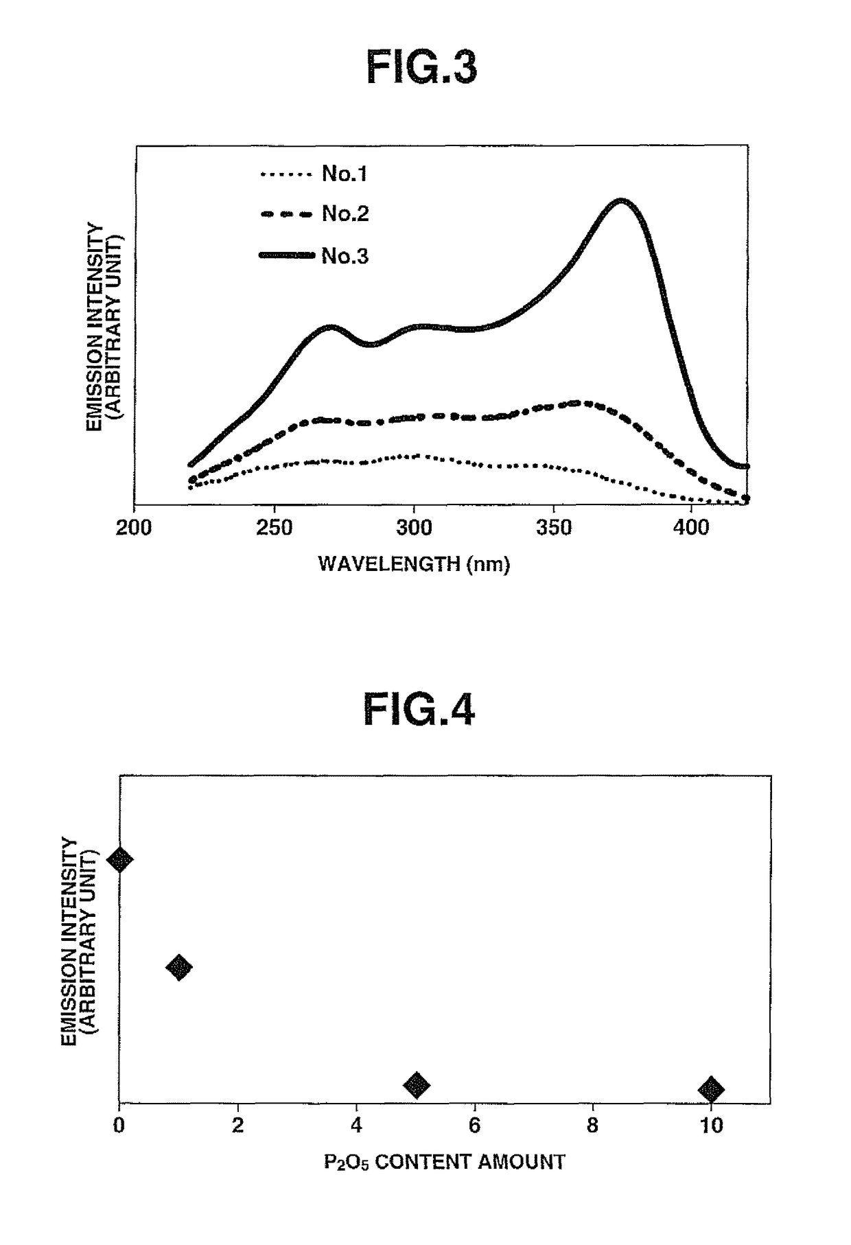
[0068]Samples No. 2 to No. 8 were obtained in the same manner as in Comparative Example 1 except for preparing raw glass materials by using and mixing starting compounds at respective mol % as shown in TABLE 1. The sample No. 2 was set to the same Ba cation content as the sample No. 1 by replacing a part of BaF2 with BaCl2, whereas the samples No. 3 to No. 8 were substantially free of Ba. More specifically, the samples No. 4 and No. 5 were different in composition from the sample No. 3 in that the Ca cation content was decreased with increase in the Sr cation content. The sample No. 6 was different in that CaCl2 was used in place of BaF2. The samples No. 7 and 8 were different in composition from the sample No. 3 in that the content amount of YbF3 was increased.

[0069]

TABLE 1No.AlF3BaF2SrF2CaF2MgF2YF3BaCl21351010201014.82235510201014.82533510201014.8243510151014.8253520101014.8263510201014.8273510201014.5083510201014.2893520201014.82Internal quantum efficiency / No.SrCl2CaCl2YbF3Extern...

example 2

[0091]As mentioned above, the emission color of the sample No. 4 was purple white. A sintered body was produced as follows by adding a red phosphor to the sample No. 4 for color correction.

[0092]First, the sample No. 4 was pulverized to a powder with an average particle size of 10 μm in a nitrogen atmosphere. As the red phosphor, Eu2+:CaAlSiN3 (luminescent center wavelength: 630 nm, average particle size: 10 μm) was added in an amount of 2 wt % based on the total weight of the powder of the sample No. 4. The powder of the sample No. 4 was mixed well with the red phosphor. The resulting mixture was formed into a pellet with a diameter of 12 mm and a thickness of 0.5 mm. The pellet was sintered by heating at 430° C. for 1 minute in a nitrogen atmosphere. By this, the sintered body in which the red phosphor was mixed in the sample No. 4 was completed as a test sample.

[0093]An emission spectrum of the thus-obtained test sample was measured at an excitation wavelength of 365 nm. The meas...

example 3

[0094]A fiber was produced as follows. A core of the fiber was of AlF3-based fluoride glass into which 1500 wt ppm of divalent ytterbium ions (Yb2±) and 0.3 mass % of trivalent ytterbium ions (Yb3+) were added as rare-earth ions. A clad of the fiber was of AlF3-based fluoride glass.

[0095]The composition of the AlF3-based fluoride glass used is indicated below. In the composition, the numerals represent mol % of the respective fluorides. Further, the term “LnF” refers to the sum of the rare-earth trifluorides, including YbF3 and YF3, in the composition. The AlF3-based fluoride glass of the core was subjected to reduction to a predetermined reduction rate by flowing 112 into the atmospheric gas during the melting. (Core) ALF3: 35, LnF3: 15, MgF2: 10, CaF2: 17.5, SrF2: 13, SrCl2: 7, BaCl2: 2.5

[0096]The composition of the clad was controlled such that thus-obtained fiber had an NA of 0.15 and a cutoff wavelength of 780 nm. The fiber was 5 cm in length. The emission spectrum of this fibe...


PUM

PropertyMeasurementUnit
luminescent center wavelengthaaaaaaaaaa
wavelength rangeaaaaaaaaaa
center wavelengthaaaaaaaaaa

Abstract

A broadband emission material according to the present invention includes: a fluoride glass containing 20 to 45 mol % of AlF3, 25 to 63 mol % of alkaline-earth fluorides in total and 3 to 25 mol % of at least one fluoride of element selected from the group consisting of Y, La, Gd and Lu; and ytterbium ions incorporated in the fluoride glass as divalent rare-earth ions so as to serve as a luminescent center, wherein the fluoride glass includes 1 to 15 mol % of at least one halide of element selected from the group consisting of Al, Ba, Sr, Ca and Mg and element selected from the group consisting of Cl, Br and I; and wherein the alkaline-earth fluorides includes 0 to 15 mol % of MgF2, 7 to 25 mol % of CaF2, 0 to 22 mol % of SrF2 and 0 to 5 mol % of BaF2.

Description

FIELD OF THE INVENTION[0001]The present invention relates to a broadband emission material capable of emitting light over a broad band and a white light emission material using the broadband emission material.BACKGROUND ART[0002]In recent years, white LED devices have been put into use as illumination light sources in place of filament lamps. For such use, there is a demand to provide white LED devices with power saving performance and high color-rendering properties. Many of currently available white LED devices realize pseudo white light by combination of YAG-Ce yellow phosphors and GaN blue LEDs.[0003]However, the conventional combination of YAG-Ce yellow phosphors and blue LEDs faces the problem that cyan component light (up to 500 nm) and red component light (600 nm or more) are not sufficient. It is thus common practice to supplement these insufficient component lights by mixing a plurality of phosphors. For example, Patent Document 1 discloses a high-color-rendering white lig...

Claims


Application Information

Patent Timeline
Patent Type & Authority Patents(United States)
IPC IPC(8): C03C3/32C03C4/12H01S3/16H01S3/17C09K11/77C03C3/247F21V8/00H01S3/091H01L33/50
CPCC03C3/325C03C3/247C03C4/12C09K11/7774C09K11/7779G02B6/0003H01S3/091H01S3/173H01L33/501H01L33/502H01S3/1618H01S3/1631Y02B20/181Y02B20/00
Inventor OKAMOTO, HIDEYUKIKASUGA, KEN
Owner CENT GLASS CO LTD
Learn More