
Liquid ejecting head and liquid ejecting apparatus

a liquid ejecting head and liquid ejecting technology, which is applied in the field of liquid, can solve the problems of liquid thickening, limited flow path of pressure chambers or the like, and difficulty in making small longitudinal vibration piezoelectric vibrators, etc., and achieve the effect of suppressing the amount of liquid, reducing the frequency of performance, and improving the processing capability of liquid discharg

Active Publication Date: 2017-05-23
SEIKO EPSON CORP
View PDF24 Cites 0 Cited by
  • Summary
  • Abstract
  • Description
  • Claims
  • Application Information

AI Technical Summary

Benefits of technology

This invention is about a new liquid ejecting head and an apparatus that can prevent thickening of liquid, improve throughput, and reduce consumption of liquid in maintenance. The technical effects of this patent include the setting of a high flow path capacity to prevent thickening of liquid, extending the performance interval of maintenance to improve throughput and reduce liquid consumption, and supplying a liquid ejecting head that is easier to handle. By adjusting the flow path capacity and communication opening, the technical effects include improved processing capabilities and reduced liquid consumption.

Problems solved by technology

The longitudinal vibration type piezoelectric vibrator is difficult to be made small, and is generally mounted on a comparatively large liquid ejecting head.
For this reason, the capacity of the flow path of the pressure chamber or the like is limited.
However, in the type of liquid ejecting head, since the liquid (meniscus) in the nozzle is exposed to outside air, a solvent component included in the liquid evaporates, and the liquid thickens with passage of time.
Therefore, if the flushing process is performed frequently, there are problems that a processing capability (throughput) per unit time is deteriorated during the printing process, and the liquid is uselessly consumed.
For this reason, when the liquid ejecting head is mounted on the liquid ejecting apparatus, it is necessary to specifically set the flushing interval to be within a comparatively short range, and there is a problem that it is hard to handle the liquid ejecting head.

Method used


Image

  • Liquid ejecting head and liquid ejecting apparatus
  • Liquid ejecting head and liquid ejecting apparatus
  • Liquid ejecting head and liquid ejecting apparatus

Examples


Embodiment Construction

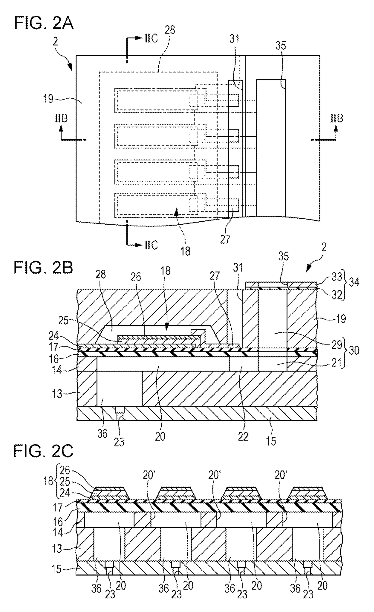
[0027]Hereinafter, an embodiment of the invention will be described with reference to drawings. In addition, in the embodiment described below, the embodiment is limited to an appropriate specific example of the invention. However, the scope of the invention is not limited thereto unless a specific description that limits the invention is mentioned. In addition, hereinafter, as an example of a liquid ejecting head of the invention, a recording head 2 will be described, which is one type of the liquid ejecting head.

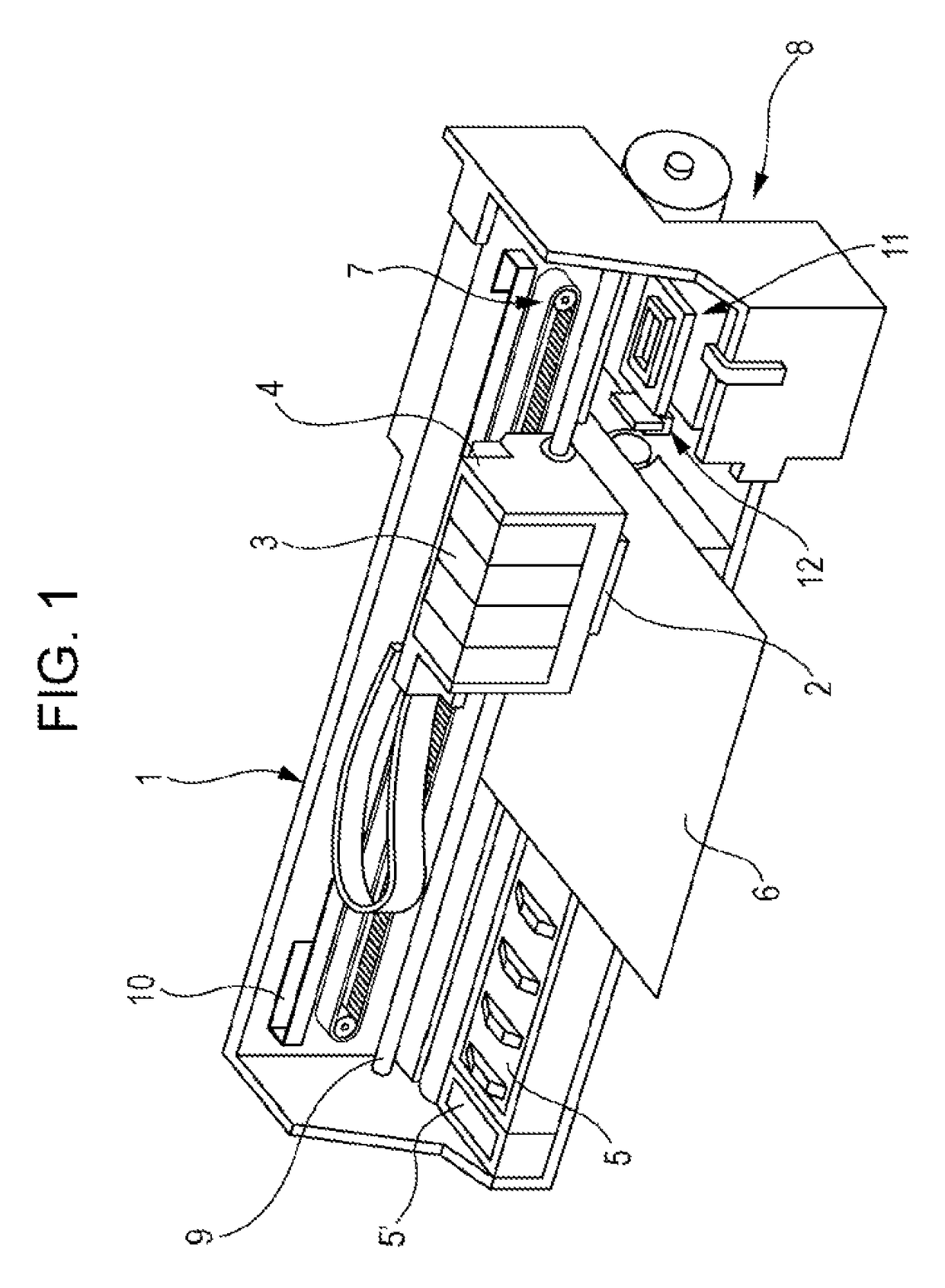
[0028]FIG. 1 is a perspective view illustrating a configuration of a printer 1. The printer 1 includes a carriage 4 to which a recording head 2 is attached and an ink cartridge 3 (which is one type of a liquid supply source) is detachably attached; a platen 5 which is disposed below the recording head 2 during a recording operation; a carriage movement mechanism 7 which reciprocally moves the carriage 4 in a paper width direction, that is, a main scanning direction of reco...


PUM


Abstract

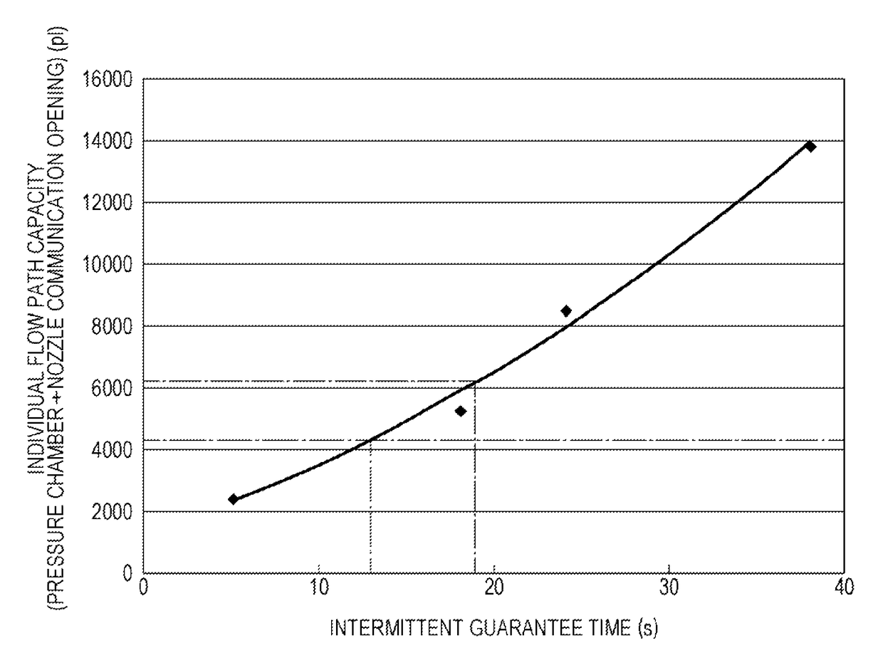
By appropriately defining a flow path capacity from an opening of an ink supply path to a nozzle in a pressure chamber, a progress of thickening ink toward the pressure chamber is suppressed. In other words, by setting the individual flow path capacity to be large, specifically, to 4400 pl or higher, desirably 6210 pl or higher, it is possible to suppress the progress of the thickening of the ink even in a small-sized liquid ejecting head of which the shortest formation pitch between each of the nozzles is 1 / 300 inches. More specifically, a nozzle communication opening is provided between the pressure chamber and the nozzle, and a total capacity of the nozzle communication opening and the pressure chamber is configured to be 4400 pl or higher, desirably 6210 pl or higher.

Description

BACKGROUND[0001]1. Technical Field[0002]The present invention relates to a liquid ejecting head (such as an ink jet type recording head) and a liquid ejecting apparatus. The invention particularly relates to a liquid ejecting head which ejects liquid introduced to a pressure chamber from a liquid supply path, from a nozzle, and relates to a liquid ejecting apparatus.[0003]2. Related Art[0004]A liquid ejecting apparatus includes a liquid ejecting head which can eject liquid as liquid droplets from a nozzle. The liquid ejecting apparatus is an apparatus which ejects various types of liquid from the liquid ejecting head. Representative examples of the liquid ejecting apparatus include an image recording apparatus, such as an ink jet type recording apparatus (printer) which has an ink jet type recording head (hereinafter, referred to as a recording head), ejects liquid ink as ink droplets from the nozzle of the recording head, and performs recording. In addition, other than that, the li...

Claims


Application Information

Patent Timeline
Patent Type & Authority Patents(United States)
IPC IPC(8): B41J2/14B41J2/165B41J2/145
CPCB41J2/14233B41J2/145B41J2/14201B41J2/1652B41J2/16517B41J2/16526B41J2002/16573B41J2202/11B41J2202/12
Inventor FUKUDA, SHUNYA
Owner SEIKO EPSON CORP
Learn More