Liquid crystal display substrate and liquid crystal display device
A liquid crystal display device and liquid crystal display technology, applied in the direction of nonlinear optics, instruments, optics, etc., can solve the problems of liquid crystal display devices such as weight gain, effective opening ratio reduction, and thickening, so as to prevent weight and thickening, prevent Effect of reduced aperture ratio and effective field of view control
- Summary
- Abstract
- Description
- Claims
- Application Information
AI Technical Summary
Problems solved by technology
Method used
Image
Examples
no. 1 Embodiment approach )
[0039] In this embodiment mode, a normally black (normally black) liquid crystal display device including initially vertically aligned liquid crystals or initially horizontally aligned liquid crystals will be described. In this embodiment, the structure of a sub-pixel unit will be described. However, the same configuration as that of the present embodiment can also be applied in units of pixels.
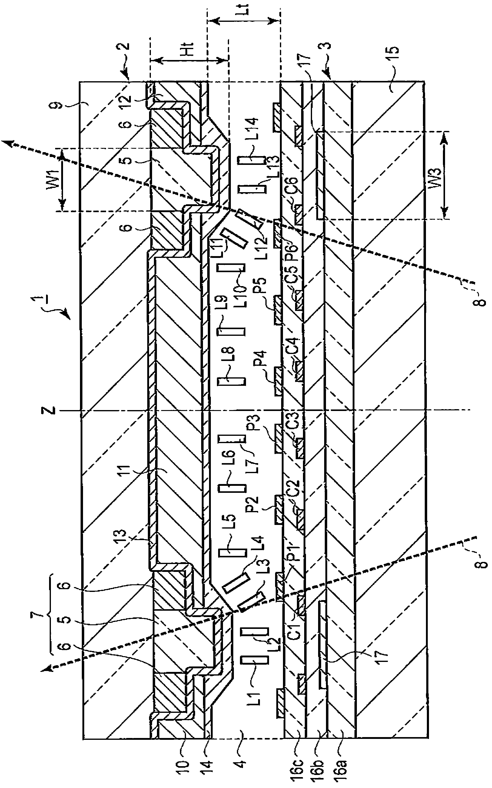
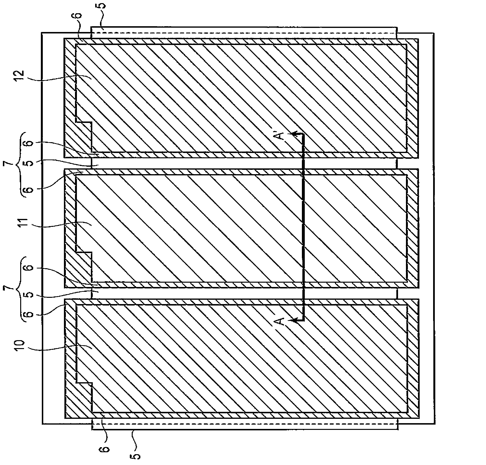
[0040] figure 1 It is a partial cross-sectional view showing an example of the liquid crystal display device of the present embodiment. Should figure 1 It is a cross-section perpendicular to the comb-tooth axis of the comb-tooth-shaped (for example, strip-shaped) electrode. exist figure 1 In the figure, the operation of the liquid crystals L1 to L14 caused by the liquid crystal display substrate 2 and the array substrate 3 and the oblique light 8 realized by the operation are shown. in the figure 1 In , illustration of vertical alignment film, polarizing plate, retardation plat...
no. 2 Embodiment approach )
[0100] In this embodiment, examples of various materials such as transparent resins and organic pigments used in the liquid crystal display substrate 2 of the first embodiment described above will be described.
[0101]
[0102] The photosensitive coloring composition used for forming a light-shielding layer or a colored layer contains, in addition to a pigment dispersion, a polyfunctional monomer, a photosensitive resin or a non-photosensitive resin, a polymerization initiator, a solvent, and the like. The highly transparent organic resin used in this embodiment, such as a photosensitive resin or a non-photosensitive resin, is called a transparent resin.
[0103] Transparent resins include thermoplastic resins, thermosetting resins, or photosensitive resins. As thermoplastic resins, for example: butyral resin, styrene-maleic acid copolymer, chlorinated polyethylene, chlorinated polypropylene, polyvinyl chloride, vinyl chloride-vinyl acetate copolymer, polyvinyl acetate, pol...
no. 3 Embodiment approach )
[0127] In this embodiment, the description Figure 16 An example of the manufacturing method of the substrate 2A for liquid crystal displays shown. Figure 16 The figure shows the substrate 9 of the liquid crystal display substrate 2A as the upper side and the protective layer 14 as the lower side.
[0128]
[0129] (Dispersion for forming light-shielding pattern 6)
[0130] 20 parts by mass of carbon pigment #47, 8.3 parts by mass of polymer dispersant, 1.0 parts by mass of copper phthalocyanine derivative, and 71 parts by mass of propylene glycol monomethyl ether acetate were stirred by a bead mill disperser to generate a carbon black dispersion.
[0131] (Photoresist for forming light-shielding pattern 6)
[0132] As a material of the light-shielding layer, a resist (Resist) for forming the light-shielding pattern 6 was generated using the following materials.
[0133] Carbon Black Dispersion: Pigment #47
[0134] Transparent resin (solid content 56.1% by mass)
[01...
PUM
| Property | Measurement | Unit |
|---|---|---|
| width | aaaaa | aaaaa |
| diameter | aaaaa | aaaaa |
| relative permittivity | aaaaa | aaaaa |
Abstract
Description
Claims
Application Information
 - R&D
- Intellectual Property
- Life Sciences
- Materials
- Tech Scout
- Unparalleled Data Quality
- Higher Quality Content
- 60% Fewer Hallucinations
Browse by: Latest US Patents, China's latest patents, Technical Efficacy Thesaurus, Application Domain, Technology Topic, Popular Technical Reports.
© 2025 PatSnap. All rights reserved.Legal|Privacy policy|Modern Slavery Act Transparency Statement|Sitemap|About US| Contact US: help@patsnap.com


