Liquid discharging apparatus
a technology of liquid discharging apparatus and liquid discharging chamber, which is applied in the direction of printing, other printing apparatus, etc., can solve the problems of image quality reduction, etc., and achieve the effect of effective drying
- Summary
- Abstract
- Description
- Claims
- Application Information
AI Technical Summary
Benefits of technology
Problems solved by technology
Method used
Image

Examples
embodiment 1
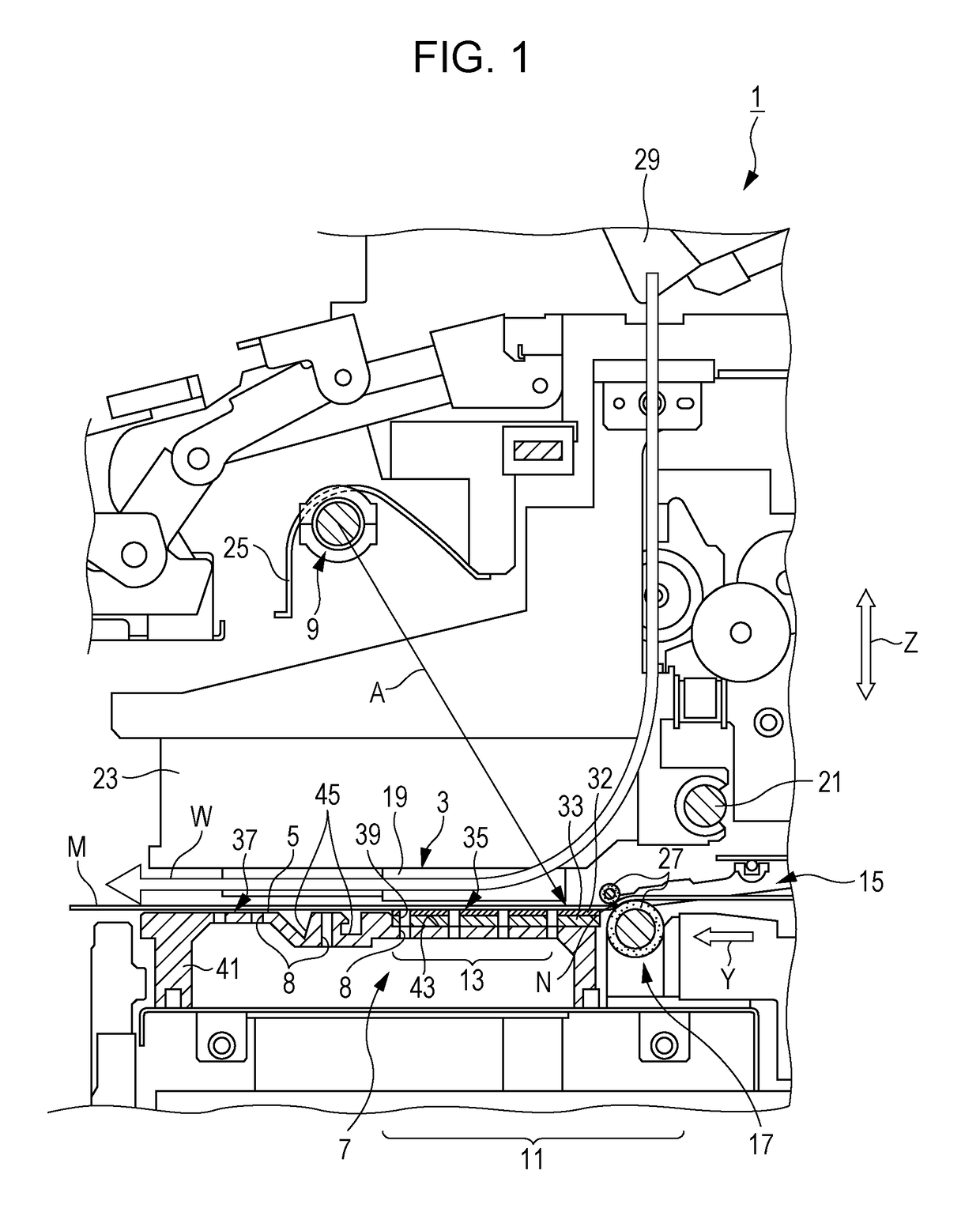
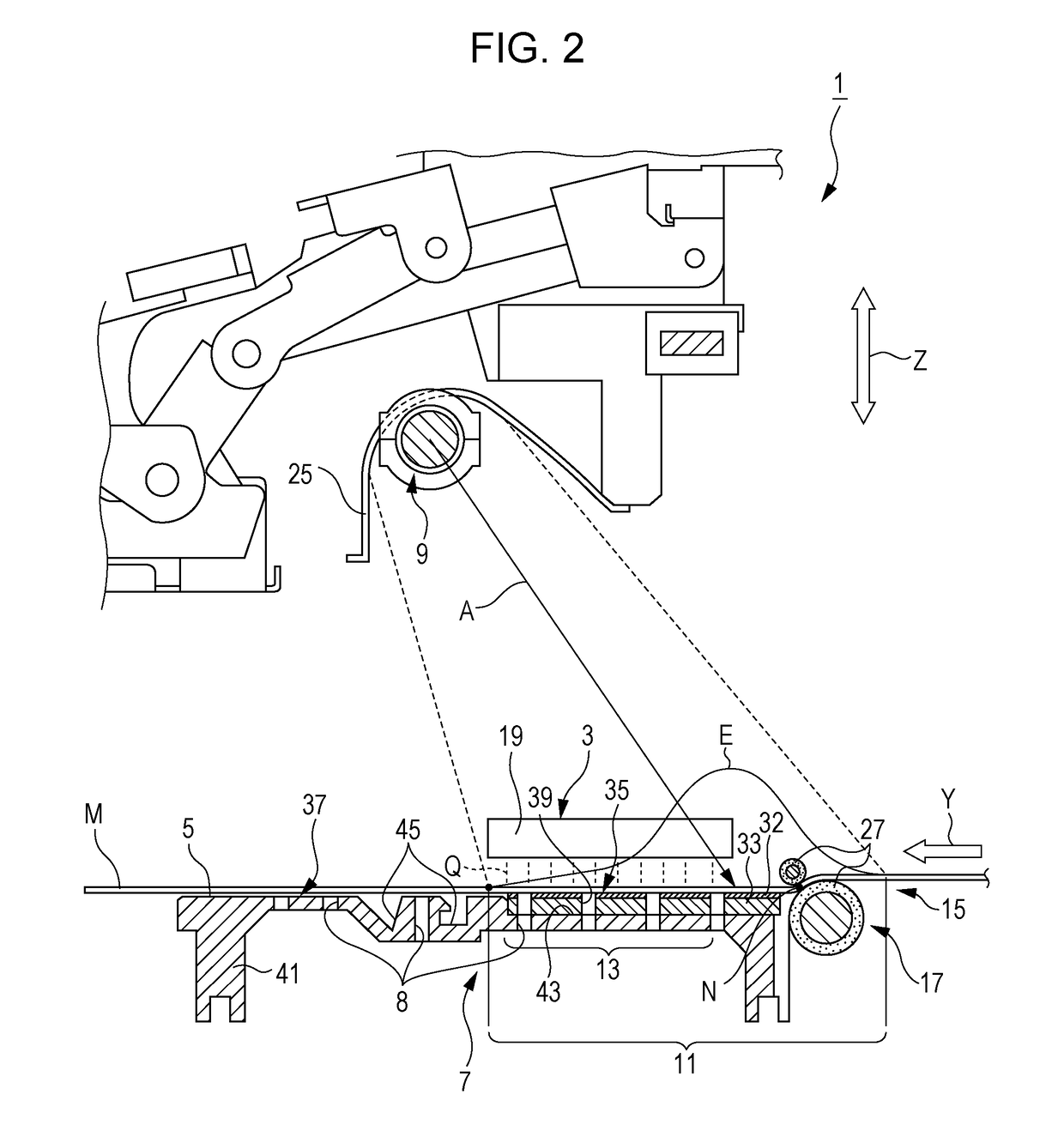
See FIGS. 1 to 6
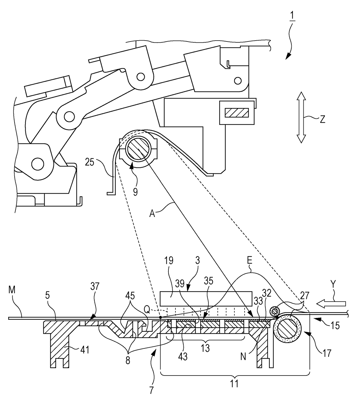
[0050]First, (1) the schematic configuration of a liquid discharging apparatus according to Embodiment 1 is described. Next, (2) the configuration and an operation of a medium support portion as the principal portion of the invention is described in detail.
(1) Schematic Configuration of Liquid Discharging Apparatus (See FIGS. 1 and 2)
[0051]A liquid discharging apparatus 1 according to an embodiment of the invention is basically configured to include a medium support portion 7 and a heating portion 9. The medium support portion 7 has a support surface 5 which supports a medium M onto which a liquid Q is discharged. The heating portion 9 can heat the medium M from a side opposite to the support surface 5 side of the medium M in a state where the medium M is supported by the support surface 5. In other words, the liquid discharging apparatus 1 includes the heating portion 9 which can heat the liquid Q discharged onto the medium M.
[0052]In this case, an example of the he...
embodiment 2
See FIG. 7
[0119]Next, the configuration of a liquid discharging apparatus of Embodiment 2 will be described. The basic configuration of the liquid discharging apparatus of the embodiment is the same as that of Embodiment 1, and thus the description thereof is not repeated. The configuration of a portion, in other words, a medium support portion, of which the configuration is different from that of Embodiment 1 will be described. FIG. 7 is a lateral cross-sectional view illustrating the liquid discharging apparatus of the embodiment. Specifically, FIG. 7 is a lateral cross-sectional view illustrating the medium support portion of the liquid discharging apparatus of the embodiment.
[0120]A liquid discharging apparatus 1a of the embodiment includes the discharge portion 3 (see FIG. 1), a medium support portion 7a, and the heating portion 9 (see FIG. 1). The discharge portion 3 can discharge liquid. The medium support portion 7a has the support surface 5 which can support a medium onto w...
embodiment
Supplement of Embodiment
[0126]Hereinafter, specific conditions in relation to the embodiments described above will be added.
[0127]The temperature of the medium M passing through the discharge area 13 and the heated area 11 is limited so that the value of the temperature is set to be, for example, about 50° C., as described above. Specifically, the range of about 50° C. may be a range of 35° C. to 60° C. Furthermore, it is more preferable that the range of about 50° C. is set to a range of 40° C. to 55° C. When the temperature of the medium M is set in the temperature range described above, the liquid Q discharged onto the medium M can be sufficiently dried. In other words, the liquid Q is fixed to the medium M without smearing or staining due to rubbing.
[0128]When summarizing the explanation described above, the heating portion 9 heats the liquid Q discharged onto the medium M so that the temperature thereof is within the range from 35° C. to 60° C. More specifically, the heating po...
PUM
 Abstract
Description
Claims
Application Information
 - R&D
- Intellectual Property
- Life Sciences
- Materials
- Tech Scout
- Unparalleled Data Quality
- Higher Quality Content
- 60% Fewer Hallucinations
Browse by: Latest US Patents, China's latest patents, Technical Efficacy Thesaurus, Application Domain, Technology Topic, Popular Technical Reports.
© 2025 PatSnap. All rights reserved.Legal|Privacy policy|Modern Slavery Act Transparency Statement|Sitemap|About US| Contact US: help@patsnap.com