
Electronic module with free-formed self-supported vertical interconnects

a technology of self-supporting and electrical interconnection, which is applied in the direction of cooling/ventilation/heating modification, semiconductor/solid-state device details, semiconductor devices, etc., can solve the problems of affecting the operation of rf, generating a significant amount of heat, etc., to improve thermal performance and cooling, improve the compactness of the electronic module, and effectively increase the available area for mounting such electronic components

Active Publication Date: 2017-03-21
RAYTHEON CO
View PDF26 Cites 3 Cited by
  • Summary
  • Abstract
  • Description
  • Claims
  • Application Information

AI Technical Summary

Benefits of technology

The patent describes a method of creating interconnect pillars on an electronic module that are self-supported and free-formed, meaning they do not have a fixed shape. This design improves the compactness of the module and allows for better mounting of electronic components. The interconnect pillars provide a straight path for electrical signals between components, reducing thermal and signal transmission losses. The cover substrate also acts as a cooling system and a thermal spreader, minimizing interference with the electrical / RF / DC operations. The interconnect pillars are formed by depositing a conductive filament layer-wise using additive manufacturing, providing flexibility in module design and reducing complexity.

Problems solved by technology

Electronic modules, such as radio frequency (RF) modules, contain electronic components, such as high-frequency chipsets, that may take up a considerable amount of space inside the module and may generate a significant amount of heat.
Typically, cooling is applied through the bottom of the module via a thermal mass or a restricted cold plate, which may interfere with RF operation due to the cold plate or thermal mass being in the direct path of electrical signals on the planar phased array antenna.

Method used


Image

  • Electronic module with free-formed self-supported vertical interconnects
  • Electronic module with free-formed self-supported vertical interconnects
  • Electronic module with free-formed self-supported vertical interconnects

Examples


Embodiment Construction

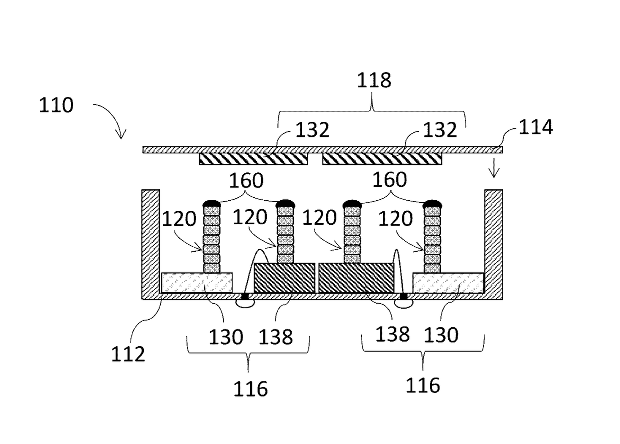
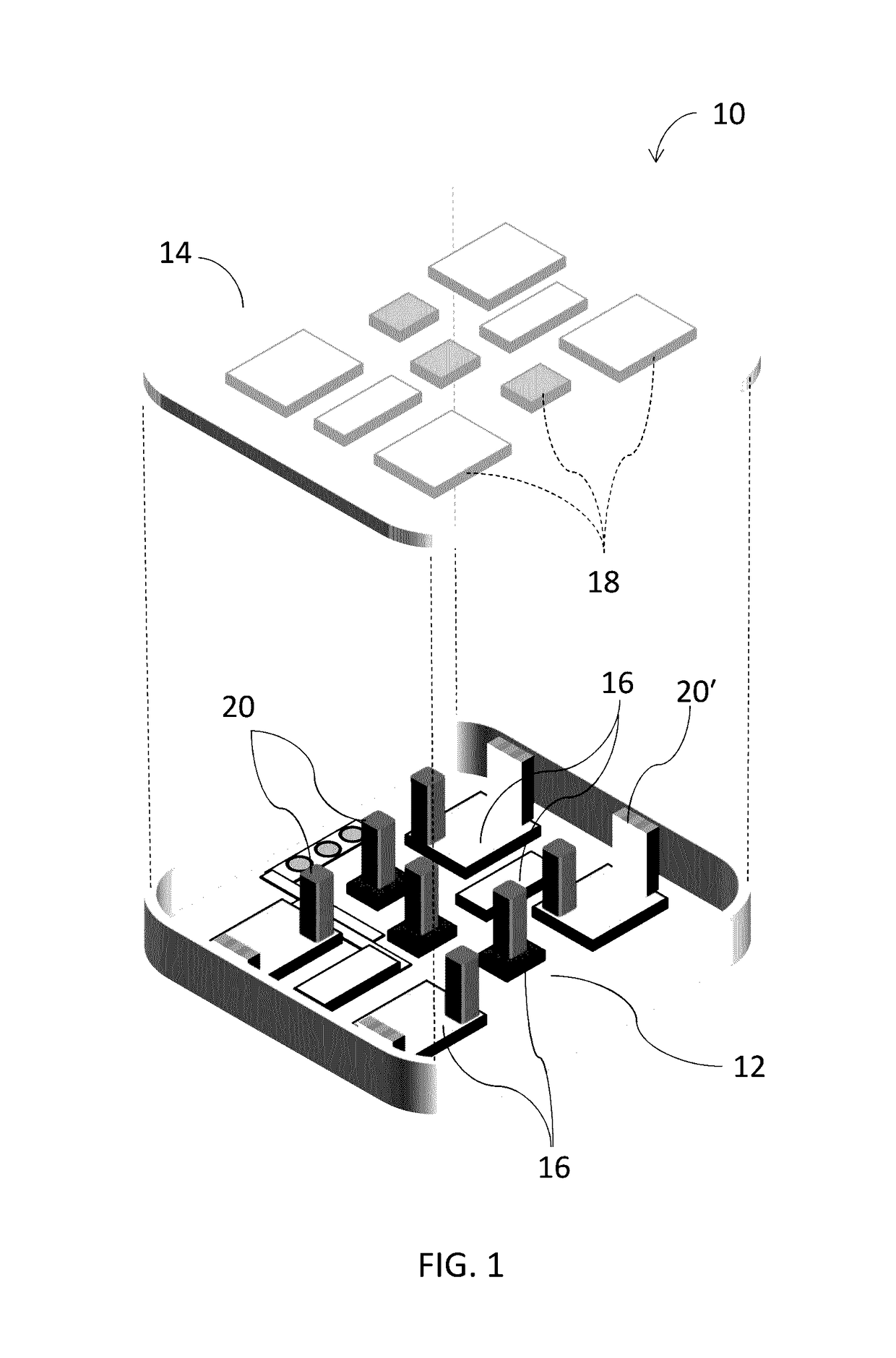
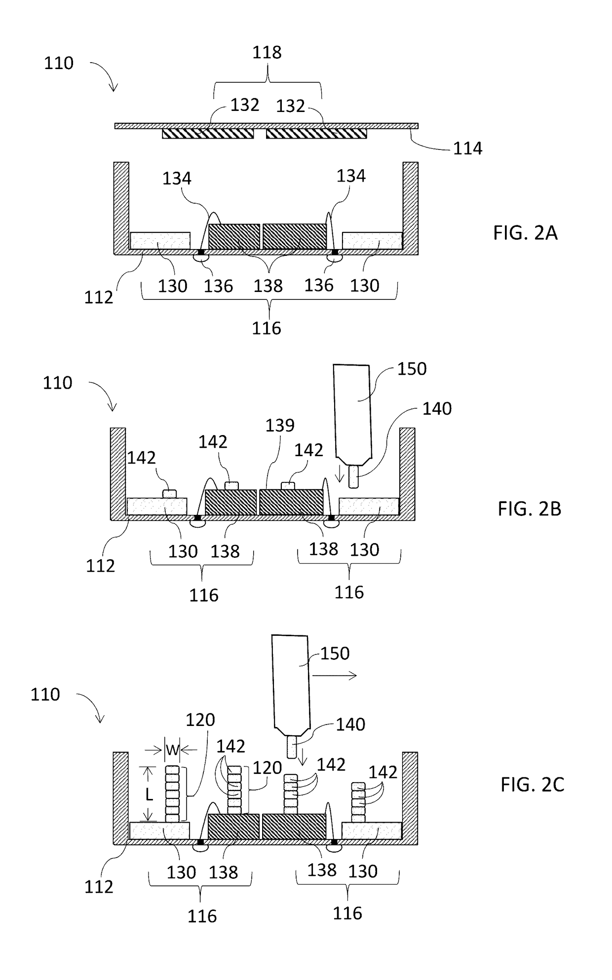
[0049]An electronic module, and method for making same, includes free-formed, self-supported interconnect pillars that electrically connect cover electronic components disposed on a cover substrate with base electronic components disposed on a base substrate. The free-formed, self-supported interconnect pillars may extend vertically in a straight path between the cover electronic components and the base electronic components. The free-formed, self-supported interconnect pillars may be formed from an electrically conductive filament provided by an additive manufacturing process.

[0050]The principles of the present invention have particular application to radio frequency (RF) electronic modules for wireless electronic devices, and thus will be described below chiefly in this context. It is also understood that principles of this invention may be applicable to other electronic modules where it is desirable to provide a three-dimensional architecture using free-formed, self-supported int...


PUM


Abstract

An electronic module, and method for making same, includes free-formed, self-supported interconnect pillars that electrically connect cover electronic components disposed on a cover substrate with base electronic components disposed on a base substrate. The free-formed, self-supported interconnect pillars may extend vertically in a straight path between the cover electronic components and the base electronic components. The free-formed, self-supported interconnect pillars may be formed from an electrically conductive filament provided by an additive manufacturing process. By free-forming the self-supported interconnect pillars directly on the electronic components, the flexibility of electronic module design may be enhanced, while reducing the complexity and cost to manufacture such electronic modules.

Description

FIELD OF INVENTION[0001]The present invention relates generally to electronic modules, and more particularly to RF modules having free-formed, self-supported electrical interconnects.BACKGROUND[0002]Electronic modules, such as radio frequency (RF) modules, contain electronic components, such as high-frequency chipsets, that may take up a considerable amount of space inside the module and may generate a significant amount of heat. RF modules in a planar phased array antenna architecture are typically mounted on a base substrate and the available area for integrating such modules is often constrained. Typically, cooling is applied through the bottom of the module via a thermal mass or a restricted cold plate, which may interfere with RF operation due to the cold plate or thermal mass being in the direct path of electrical signals on the planar phased array antenna. As electronic components for RF modules become increasingly complex, there is a need to improve the available surface are...

Claims


Application Information

Patent Timeline
Patent Type & Authority Patents(United States)
IPC IPC(8): H01L21/00H05K13/00H05K7/20
CPCH05K7/202H05K13/0023H01L23/36H01L23/66H01L24/11H01L25/0652H01L2224/16145H01L2224/73207H01L2224/9202H01L2225/0651H01L2225/06589H01L2225/06513H01L2224/92163H01L23/5385H01L2224/1308H01L2224/81901H01L24/13H01L24/16H01L24/48H01L24/72H01L24/73H01L24/81H01L24/90H01L2224/1134H01L2224/48227H01L2224/72H01L2224/81191H01L2224/90H05K13/00H01L2224/85H01L2224/11
Inventor PILLANS, BRANDON W.MCSPADDEN, JAMES
Owner RAYTHEON CO
Learn More