
Unified optimization method for end-to-end camera image processing for translating a sensor captured image to a display image

a technology of end-to-end camera image processing and display image, which is applied in the direction of image enhancement, geometric image transformation, instruments, etc., can solve the problems of introducing cumulative errors, complicated process of reconstructed photograph from raw sensor measurements, and exacerbated approach

Active Publication Date: 2017-01-31
NVIDIA CORP
View PDF14 Cites 3 Cited by
  • Summary
  • Abstract
  • Description
  • Claims
  • Application Information

AI Technical Summary

Benefits of technology

This approach prevents error accumulation, enhances image quality, and allows for efficient implementation on GPUs, making it adaptable to different camera designs and applications, while maintaining high performance and reducing computational complexity.

Problems solved by technology

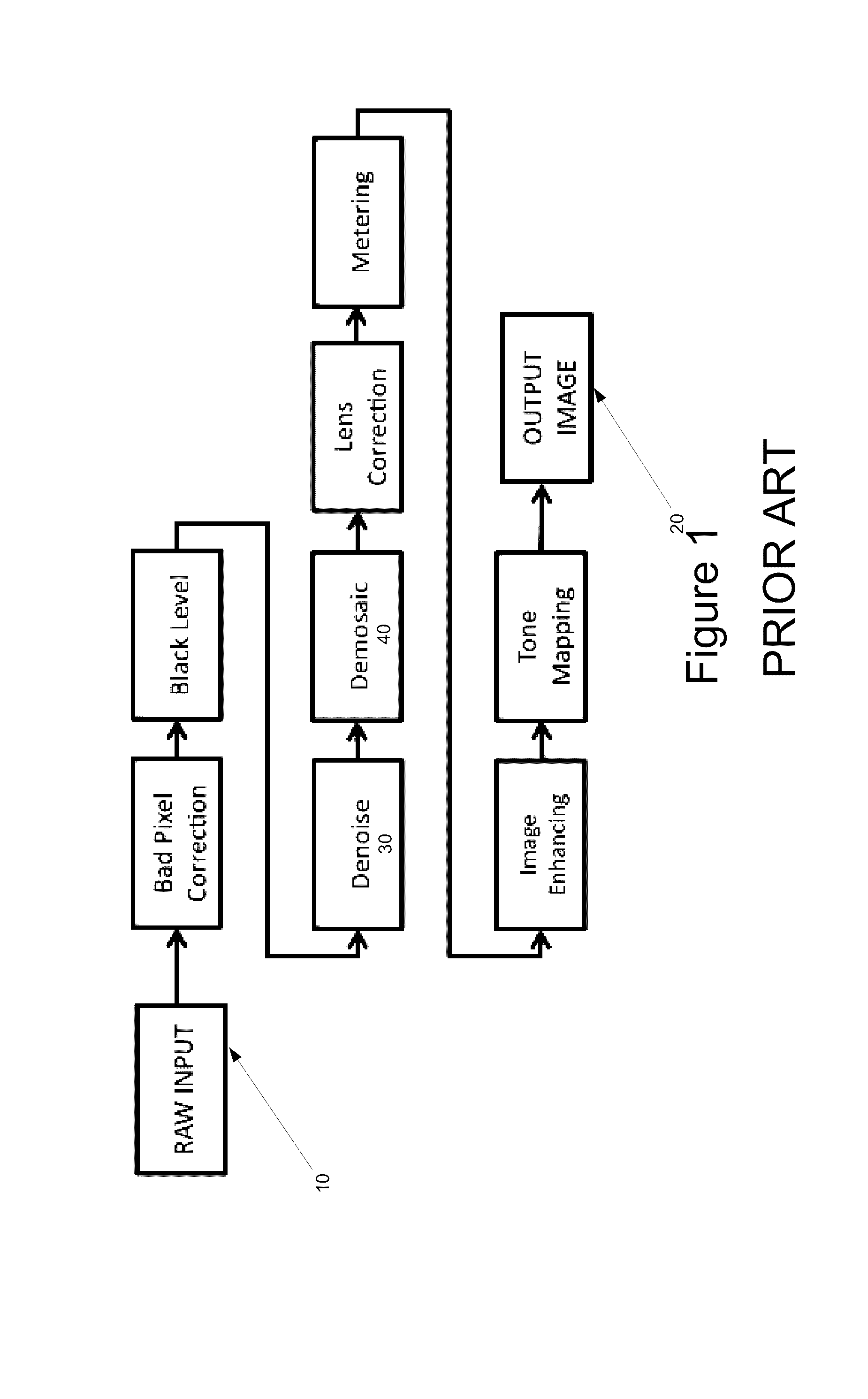
Even with relatively simple camera designs, reconstructing a photograph from raw sensor measurements is a complicated process that involves many complex tasks, including dead-pixel elimination, noise removal, spatial upsampling of subsampled color information (e.g., demosaicking of Bayer color filter arrays), sharpening and image compression.
First, most of the individual stages are mathematically ill-posed and rely heavily on heuristics and prior information to produce good results. The following stages then treat the results of these heuristics as ground-truth input, aggregating the mistakes through the pipeline. In other words, while the pipeline approach offers many of the benefits of the classic divide-and-conquer methodology, it also introduces a cumulative error, as each step in the pipeline only considers the output of the previous step, not the raw sensor data. The results of this cumulative error include artifacts such as noise residual, zipper artifacts, or color fringing, etc.
Secondly, the individual stages of the pipeline are in fact not truly independent, and there often exists no natural order in which the stages should be processed. For example, if denoising 30 follows demosaicking 40 in the pipeline, the demosaicking step must be able to deal with noisy input data when performing edge detection and other such tasks required for upsampling of the color channels. All these challenges of the pipeline approach are exacerbated by more complex image processing needs in modern computational cameras.
Further, another problem with current ISPs is that their architecture is rigid and, therefore, implementing new computational photography applications is not straightforward or efficient.
Because the ISP pipeline is implemented in hardware and is specific to one design it is not easily portable to different hardware implementations, e.g., different camera models, etc.
For example, several new photography applications and camera types have been developed that deviate from a regular Bayer image capture and, therefore, map poorly to the rigid design of current ISPs.

Method used


Image

  • Unified optimization method for end-to-end camera image processing for translating a sensor captured image to a display image
  • Unified optimization method for end-to-end camera image processing for translating a sensor captured image to a display image
  • Unified optimization method for end-to-end camera image processing for translating a sensor captured image to a display image

Examples


Embodiment Construction

[0036]Reference will now be made in detail to the various embodiments of the present disclosure, examples of which are illustrated in the accompanying drawings. While described in conjunction with these embodiments, it will be understood that they are not intended to limit the disclosure to these embodiments. On the contrary, the disclosure is intended to cover alternatives, modifications and equivalents, which may be included within the spirit and scope of the disclosure as defined by the appended claims.

[0037]Furthermore, in the following detailed description of the present disclosure, numerous specific details are set forth in order to provide a thorough understanding of the present disclosure. However, it will be understood that the present disclosure may be practiced without these specific details. In other instances, well-known methods, procedures, components, and circuits have not been described in detail so as not to unnecessarily obscure aspects of the present disclosure.

[0...


PUM


Abstract

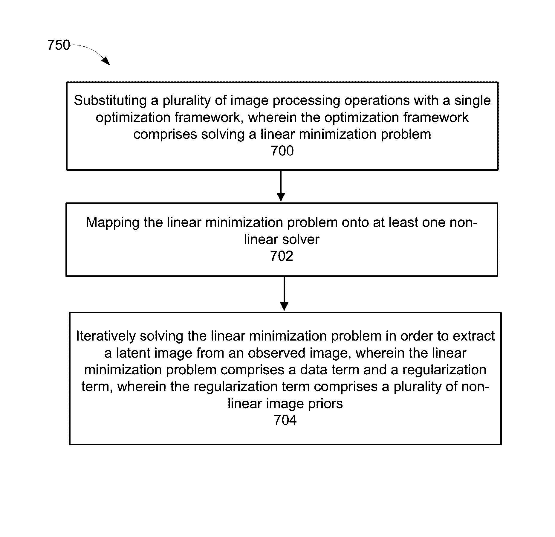
A computer implemented method of determining a latent image from an observed image is disclosed. The method comprises implementing a plurality of image processing operations within a single optimization framework, wherein the single optimization framework comprises solving a linear minimization expression. The method further comprises mapping the linear minimization expression onto at least one non-linear solver. Further, the method comprises using the non-linear solver, iteratively solving the linear minimization expression in order to extract the latent image from the observed image, wherein the linear minimization expression comprises: a data term, and a regularization term, and wherein the regularization term comprises a plurality of non-linear image priors.

Description

CROSS-REFERENCE TO RELATED APPLICATIONS[0001]This application is a conversion of and claims priority to and the benefit of Provisional Patent Application No. 61 / 929,889, entitled “UNIFIED OPTIMIZATION METHOD FOR END-TO-END CAMERA IMAGE PROCESSING,” having a filing date of Jan. 21, 2014, which is herein incorporated by reference in its entirety.FIELD OF THE INVENTION[0002]Embodiments according to the present invention generally relate to graphics processing units (GPUs) and more specifically to rendering high-quality digital images using GPUs.BACKGROUND OF THE INVENTION[0003]Modern camera systems rely heavily on computational processing to produce high-quality digital images. Even with relatively simple camera designs, reconstructing a photograph from raw sensor measurements is a complicated process that involves many complex tasks, including dead-pixel elimination, noise removal, spatial upsampling of subsampled color information (e.g., demosaicking of Bayer color filter arrays), sh...

Claims


Application Information

Patent Timeline
Patent Type & Authority Patents(United States)
IPC IPC(8): G09G5/02G09G5/36G06T5/00
CPCG09G5/02G06T5/001G09G5/026G09G5/363G09G2320/0238G09G2320/0242G09G2320/0247G09G2360/08G06T5/00G06T5/70G06T3/4015G09G2320/066
Inventor PAJAK, DAWID STANISLAWHEIDE, FELIXREDDY, NAGILLA DIKPALROUF, MUSHFIQURKAUTZ, JANPULLI, KARIGALLO, ORAZIO
Owner NVIDIA CORP
Learn More