
System and method for preserving back-up battery for improved back-up availability

a backup battery and backup technology, applied in the field of power management circuits, can solve the problems of difficult qualification of devices, high current consumption of battery monitoring/management devices available in the market, and potential explosive atmospher

Active Publication Date: 2019-07-02
INNOVATION ASSET COLLECTIVE
View PDF22 Cites 0 Cited by
  • Summary
  • Abstract
  • Description
  • Claims
  • Application Information

AI Technical Summary

Benefits of technology

[0011]It is another aspect of the disclosed embodiments to provide for a back-up battery circuit having a minimum leakage current to ensure a long battery operating life.
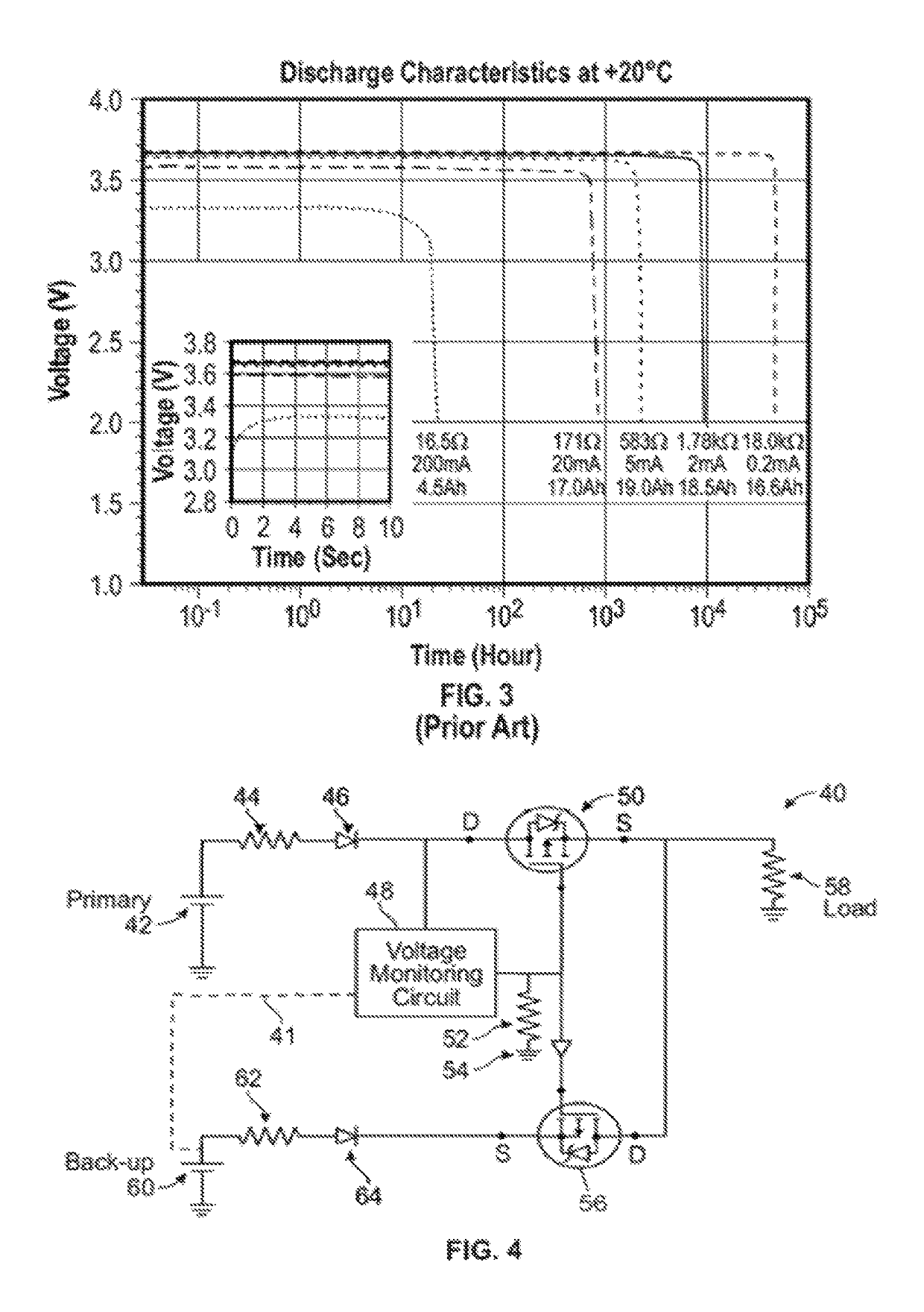
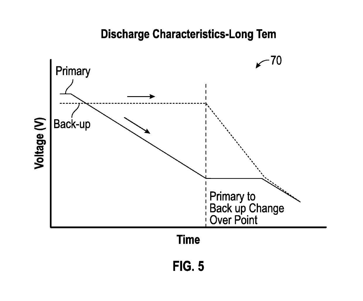
[0014]In an example embodiment, the voltage monitoring circuit can be configured with the ability to judge the battery profile / condition, based on various physical variables such as temperature, which can affect the threshold voltage to switchover to the backup battery. The voltage monitoring circuit can also monitor the voltage of the backup battery to ensure and inform the system that the backup battery is in good condition and can be utilized during a power outage. The voltage monitoring circuit can further keep track of the amount of backup battery used up during a power outage / switchover and indicate whether the backup battery is healthy or needs to be replaced.

Problems solved by technology

A potentially explosive atmosphere exists when a mixture of air gases, vapors, mists, or dusts combine in a manner that may ignite under certain operating conditions.
A general observation can be made that battery monitoring / management devices available in the market consume very high currents for their own operations.
Conserving this leaky current becomes very critical in battery-operated devices, which are expected to last in some cases for many years.
The use of complex devices for critical functions such as dealing with two or more power sources makes such devices difficult to qualify, for example, for Ex (Explosive Protection) requirements (e.g., hazardous area certifications).
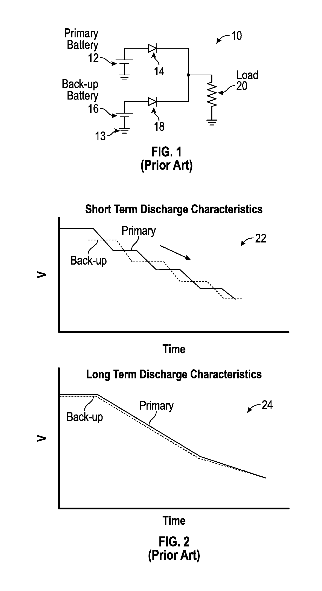
Diode-based solutions such as circuit 10 depicted in FIG. 1 come with a built-in disadvantage because in such devices, the discharge rate is low and the life of the main battery 12 is expected to be long (e.g., at least several years).
This issue is particularly evident when both batteries are of the same type.
The discharge of these batteries is very steep during the last part of the cycle and this is where above-mentioned issues become a concern.

Method used


Image

  • System and method for preserving back-up battery for improved back-up availability
  • System and method for preserving back-up battery for improved back-up availability
  • System and method for preserving back-up battery for improved back-up availability

Examples


Embodiment Construction

[0021]The particular values and configurations discussed in these non-limiting examples can be varied and are cited merely to illustrate one or more embodiments and are not intended to limit the scope thereof.

[0022]Subject matter will now be described more fully hereinafter with reference to the accompanying drawings, which form a part hereof, and which show, by way of illustration, specific example embodiments. Subject matter may, however, be embodied in a variety of different forms and, therefore, covered or claimed subject matter is intended to be construed as not being limited to any example embodiments set forth herein; example embodiments are provided merely to be illustrative. Likewise, a reasonably broad scope for claimed or covered subject matter is intended. Among other things, for example, subject matter may be embodied as methods, devices, components, or systems. Accordingly, embodiments may, for example, take the form of hardware, software, firmware, or any combination ...


PUM


Abstract

A battery management system comprising a main battery and a backup battery. A load is electrically connected to the main battery and the backup battery through one or more switches (e.g., FET switches). A voltage monitoring circuit is electrically connected to the main battery, the backup battery, and the load, wherein the voltage monitoring circuit monitors a voltage from the main battery and triggers a changeover to the backup battery based on a threshold and wherein a main battery interface path within the circuit is facilitated by a bypass diode for automatically switching the circuit to avoid power interruptions.

Description

TECHNICAL FIELD[0001]Embodiments are related to power management circuits. Embodiments are also related to electronic devices and secondary or battery back-up circuits.BACKGROUND[0002]Oil and natural gas industry products, like many other electronics products, utilize a wide range of electrical and electromechanical machines and products, many of which are installed in hazardous locations including explosive atmospheric environments. A potentially explosive atmosphere exists when a mixture of air gases, vapors, mists, or dusts combine in a manner that may ignite under certain operating conditions. Equipment and protective systems intended for use in potentially explosive atmospheres (e.g., ATEX / IEC) cover a range of products, including those utilized in, for example, fixed offshore platforms, petrochemical plants, mines, and flour mills, amongst others. Products implemented in such conditions are defined by ATEX standards.[0003]Many of these products are battery operated and support...

Claims


Application Information

Patent Timeline
Patent Type & Authority Patents(United States)
IPC IPC(8): H02J7/00H02J9/00H02J1/10H02J9/06
CPCH02J9/06H02J9/061H02J7/0063H02J1/108
Inventor KUMAR K N, DINESHSATHYANARYANA RAO, ARAVIND HULISANDRABLEIER, WOLFGANG
Owner INNOVATION ASSET COLLECTIVE
Learn More