
On-site verification of implant positioning

a technology of implant positioning and onsite verification, which is applied in the field of intraoperative fluoroscopic imaging of orthopedic implants, can solve the problems of difficult to interpret x-ray images, difficult to perform verification, and weak contrast, and achieve high contrast implants, high contrast, and high accuracy. the effect of accuracy

Active Publication Date: 2017-01-17
MAZOR ROBOTICS
View PDF35 Cites 21 Cited by
  • Summary
  • Abstract
  • Description
  • Claims
  • Application Information

AI Technical Summary

Benefits of technology

The patent describes a system that uses a combination of preoperative and intraoperative images to improve the accuracy and reliability of orthopedic surgery procedures. The system analyzes the images to determine the position and orientation of the surgical instruments relative to the patient's anatomy. This information is then used to accurately display the position of the instruments in the preoperative images, which would have been obtained without the instruments. This method allows the surgeon to make informed decisions during the operation without the need for post-operative CT images. Overall, this system improves the accuracy and efficiency of orthopedic surgery procedures.

Problems solved by technology

However, such verification may be difficult to perform since although the implants, generally being metallic, show up with high contrast in the intra-operative x-ray images, the anatomical features around them may have much weaker contrast, and, because of the depth of soft tissue and bone through which the x-ray image is being taken, various image artifacts may make the X ray image difficult to interpret.
Consequently, in the typically blurred fluoroscope image, it may be difficult to associate the position of the implant with the unclearly defined surrounding bone structure into which the insert has been placed.
Currently this is a problematic situation, since the verification of an implant location can only be performed after closing the operating site, and sending the patient for a high definition 3-D imaging procedure, such as a CT or an MRI procedure, in which the soft tissues and bone are also clearly defined.
If this procedure shows that the implant is not in the correct position, then the patient must undergo a correction operation, with its associated discomfort and costs.
This problem is particularly acute in spinal operations, such as those which use pedicle screws for spinal fusion for instance, the accuracy of the placement of the screws being highly critical because of the proximity of sensitive neurological features.
Because of the complex orthopedic structural nature of the vertebrae themselves and of their associated muscles and ligaments, determination of the spatial position and angle of a pedicle screw is difficult to define in a two-dimensional x-ray image.
However whereas the preoperative CT images should show all of the anatomical features clearly delineated, the intraoperative virtual CT may not show all of these anatomical features clearly, because of the above-mentioned problems associated with the fluoroscopic imaging of a complex operating site with complex and thick layers of soft tissue together with the bone and the insert.
More importantly, whenever a comparatively large radiographically opaque object is imaged (“comparatively large” meaning of size comparable with the size of the details to be discerned), artifacts are generated because the high contrast implant “shadows” the image details.
However, such implementations are likely to be limited.
In particular, they are unlikely to be useful for spinal procedures, since the best orientation for determining the accuracy of positioning of a pedicle screw is the axial plane.
When applied to the verification of the positioning of a pedicle screw implant in the subject's spine, the system and method uses imagery from existing C-arms, which are standard equipment in spine operating rooms, as opposed to either waiting for a post operative CT scan, or using an additional, expensive intra-operative 3D system installed in the spine surgery operating room.

Method used


Image

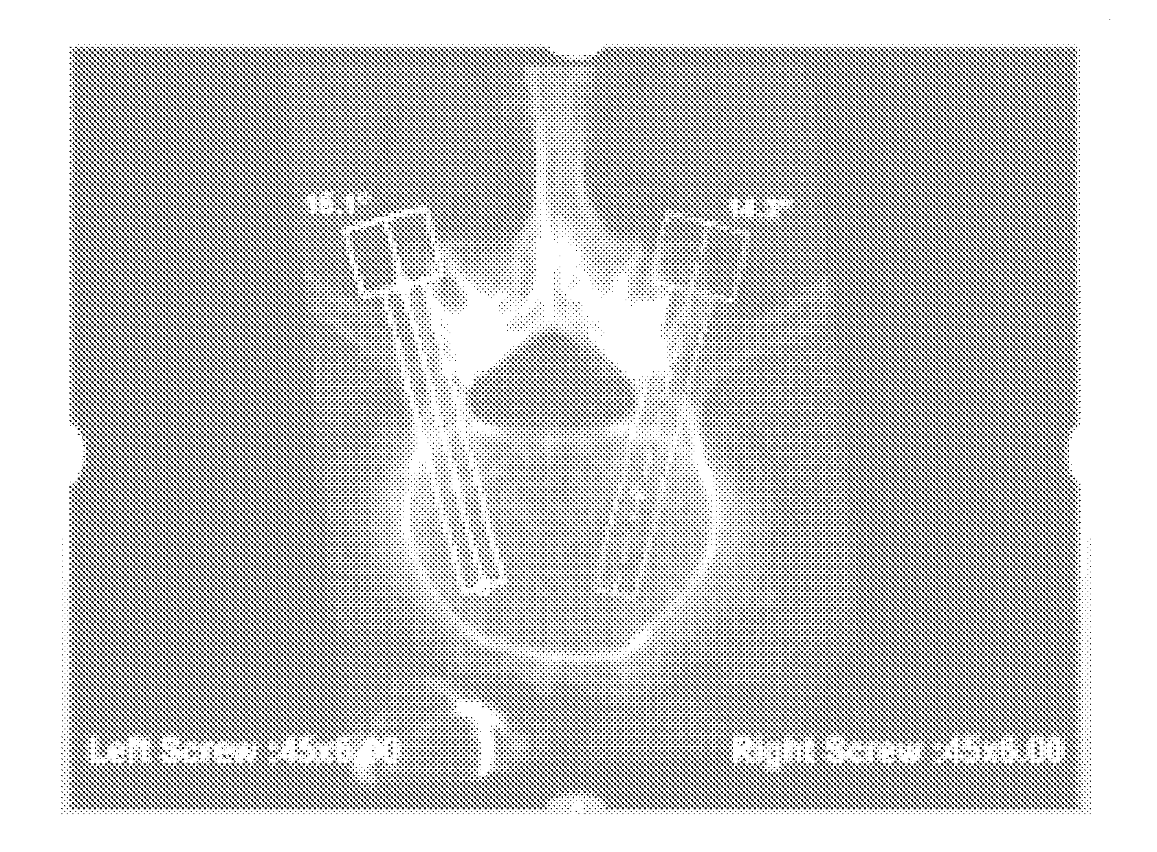
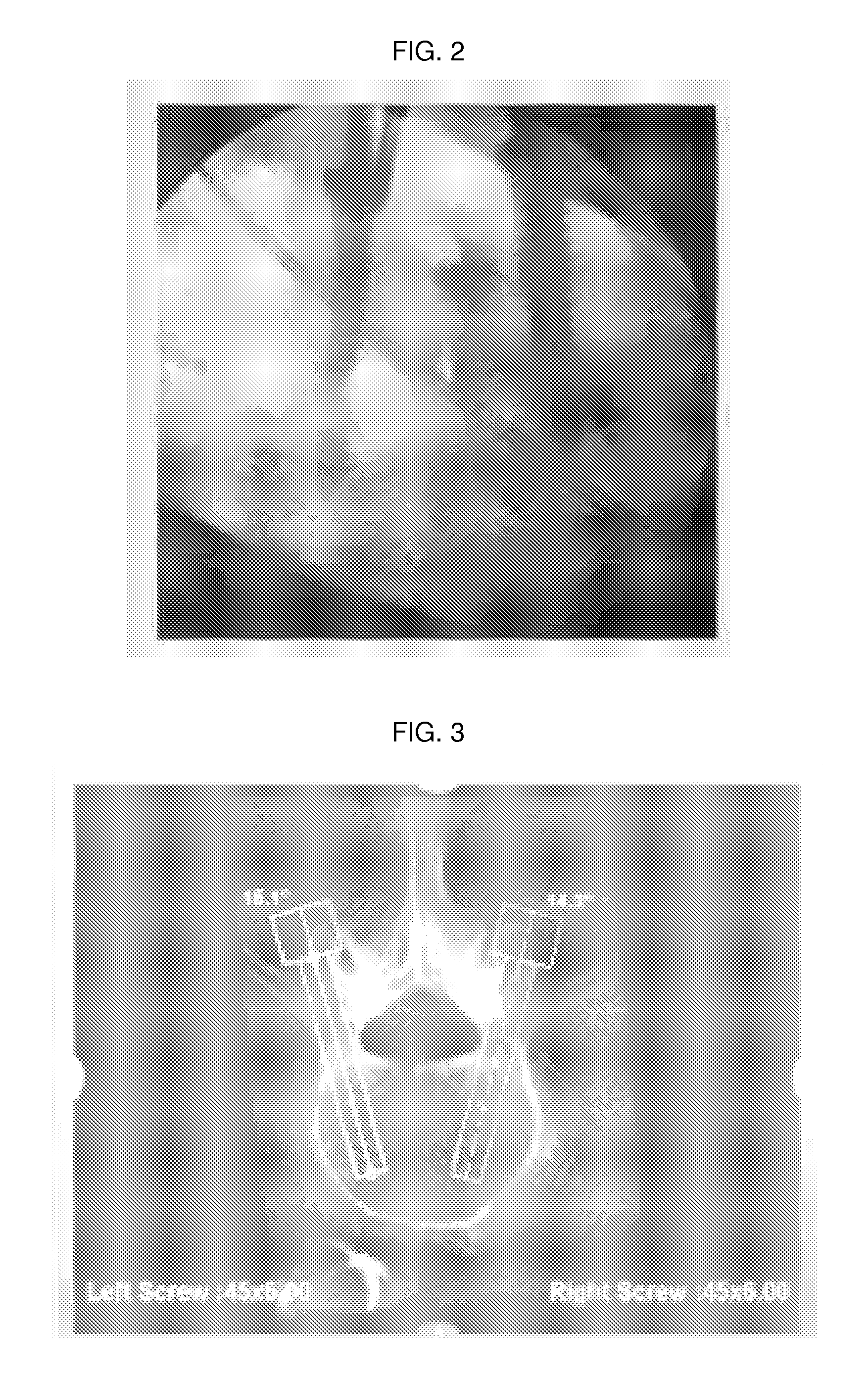
  • On-site verification of implant positioning
  • On-site verification of implant positioning
  • On-site verification of implant positioning

Examples


Embodiment Construction

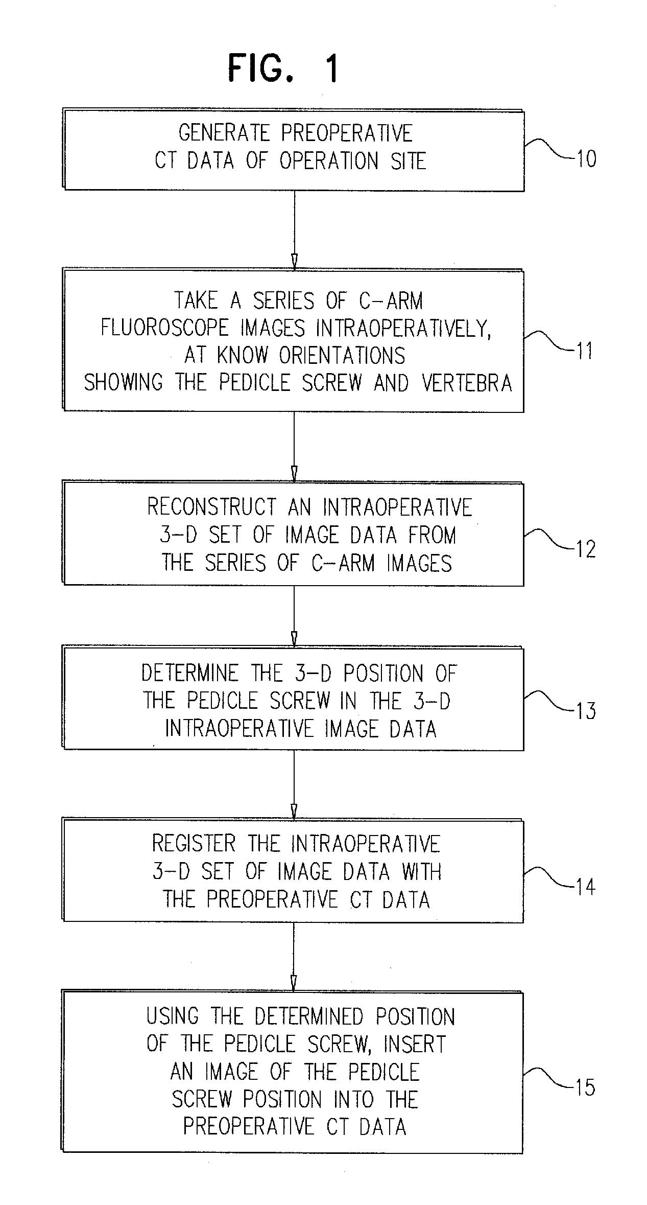
[0042]Reference is now made to FIG. 1, which illustrates schematically a flow chart describing an exemplary method of the present application, by which the position of a vertebral pedicle screw can be accurately determined intraoperatively from a number of two-dimensional C-arm images taken in the operating room. Although the procedure is described in terms of imaging using a C-arm, this is understood to be only one method by which it is possible to obtain a series of two-dimensional intraoperative images at known orientations, and the disclosure is not intended to be limited to use of the C-arm method.

[0043]In step 10, a preoperative CT set of images of the operation site is generated and stored in the control system memory. The surgeon may then plan the intended position of the pedicle screw insert on this set of three dimensional preoperative images.

[0044]In step 11, a series of C-arm fluoroscope images are taken intraoperatively at known orientations of the C-arm, the images sho...


PUM


Abstract

A method verifying the position of a surgically inserted orthopedic insert. A preoperative three dimensional image data set of the surgical site is generated, showing the bone into which the insert is to be inserted. During the insertion procedure, a series of intraoperative two-dimensional fluoroscope images are generated, each at a known pose relative to the bone, showing the insert during or after insertion into the bone. The 3-D position of the insert is determined in an intraoperative three dimensional image data set reconstructed from the series of intraoperative 2-D fluoroscope images. The reconstructed intraoperative 3-D image data set is registered with the preoperative three dimensional image data set, such as by comparison of imaged anatomical features. Once this registration is achieved, the determined 3-D position of the insert is used to implant a virtual image of the insert into the preoperative three dimensional image data set.

Description

[0001]This is a 35 U.S.C. §371 application of PCT / IL2013 / 050437, filed May 21, 2013, and claims the benefit under 35 U.S.C. §120 of said PCT application, and further claims the benefit under 35 U.S.C. §119(e) of U.S. Provisional Patent Application USSN 61 / 650242, filed May 22, 2012. The contents of these priority applications are incorporated herein by reference.FIELD OF THE INVENTION[0002]The present invention relates to the field of intraoperative fluoroscopic imaging of orthopedic implants, and especially for use in verifying the spatial accuracy of the position of the implant during the course of the operation.BACKGROUND OF THE INVENTION[0003]In orthopedic surgery, intraoperative fluoroscopic images are extensively used in order to ascertain the alignment of orthopedic implants, such that they are inserted into their predetermined positions, as selected by the surgeon generally using preoperative three-dimensional images, such as CT images. Such intra-operative fluoroscopic imag...

Claims


Application Information

Patent Timeline
Patent Type & Authority Patents(United States)
IPC IPC(8): G06K9/00A61B6/00A61B6/12G06K9/62G06T15/00G06T7/00
CPCA61B6/12A61B6/5235A61B6/5247A61B90/36G06K9/6202G06T7/70G06T15/00A61B2090/364A61B2090/367A61B2090/376A61B2090/3966G06T2207/10121G06T2207/30008
Inventor SIRPAD, YAELZEHAVI, ELISHOHAM, MOSHEKLEYMAN, LEONID
Owner MAZOR ROBOTICS
Learn More