
High-brightness LPP EUV light source

Active Publication Date: 2016-10-25
ISTEQ BV
View PDF1 Cites 15 Cited by
  • Summary
  • Abstract
  • Description
  • Claims
  • Application Information

AI Technical Summary

Benefits of technology

The invention improves the reliability and lifespan of the EUV light source, simplifies its construction, and lowers its cost of ownership while providing high brightness, high spatial and energy stability.

Problems solved by technology

In the case of mask defect occurrence, defects are projected onto the silicon wafer / substrate which has photoresist hence contributing to the occurrence of micro print defects on the wafer.
The common approach in lithography manufacturing is moving away from IC analysis, which is excessively labor and cost intensive at high volume manufacturing, to the analysis of lithographic masks.
Zero defect control of lithographic masks during manufacturing and operating is one of the key problems in EUV lithography.
However, Z-pinch is produced in the SiC ceramic bush with orifice diameter 3 mm, which makes it necessary repeated periodic replacement because of significant erosion.
There are several disadvantages in using this technology: low efficiency of target material, high price of xenon, complicated system of recycling, necessity of high linear speed >15 m / s of cooled cylinder rotating and the related problem of EUV source stability, and lastly, the necessity of collector mirror protection from the effect of heavy ions in Xe-plasma.
However, such EUV sources are rather difficult and expensive due to the use of a complicated laser system with pre-pulse.
This complication arises from the laser system along with the need for target droplet synchronization and high speed gas for cooling down and protection of the collector mirror together with its electromagnetic protection system.
It makes difficult the production of commercially viable EUV sources for inspection and metrology.
However, heating of the window, necessary for its evaporative cleaning, reduces lifetime of sealing gasket and detracts from the apparatus' reliability altogether.
However, a thermal-stress resistant mirror is very expensive.
As a result, evaporative cleaning is a factor which limits the resource of the multi-layer Mo / Si mirror.

Method used


Image

  • High-brightness LPP EUV light source
  • High-brightness LPP EUV light source
  • High-brightness LPP EUV light source

Examples


Embodiment Construction

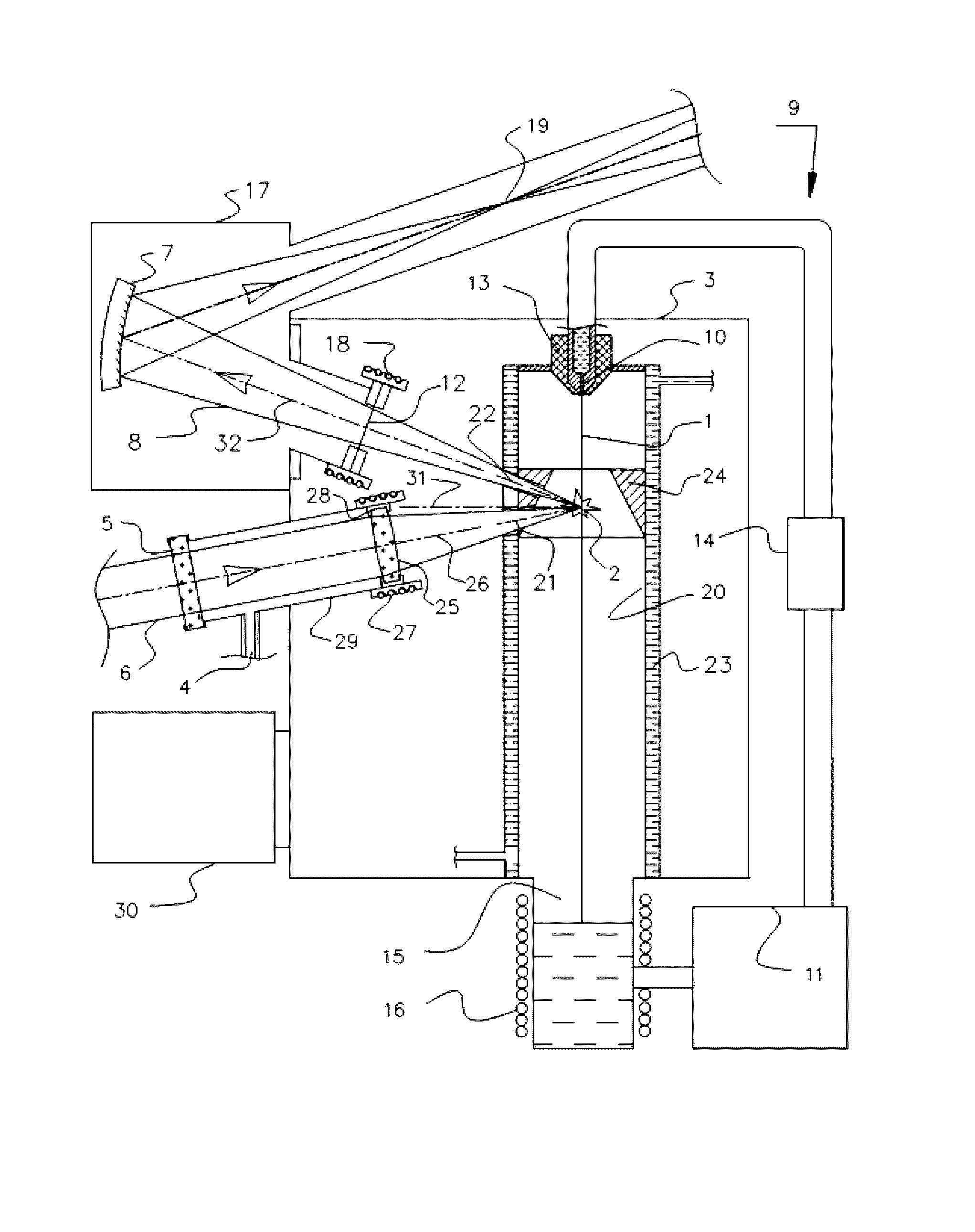
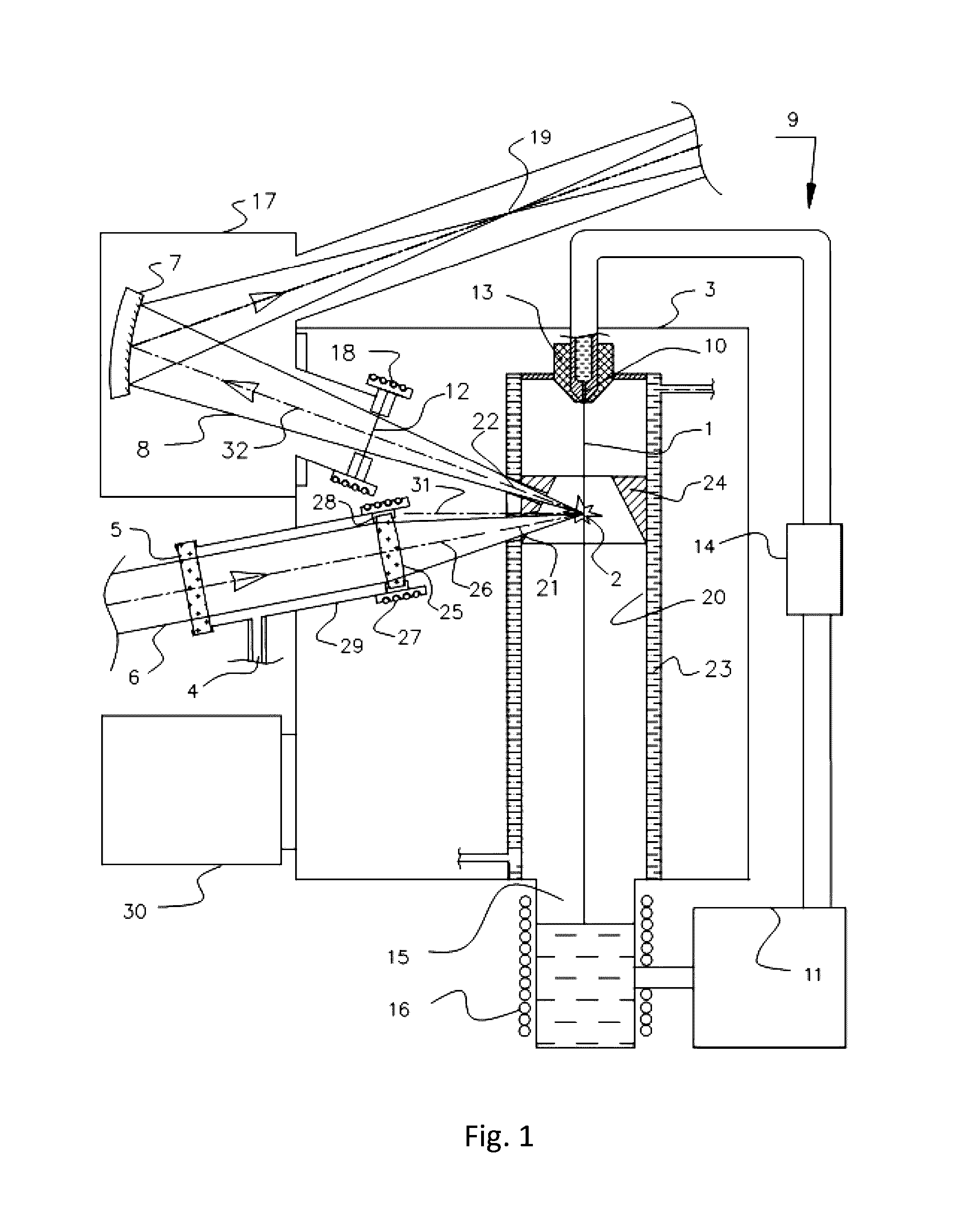
[0034]According to the preferred embodiment of the invention, illustrated schematically in FIG. 1, a high-brightness LPP EUV light source comprises a laser target 1 delivered in an interaction zone 2 in a vacuum chamber 3 containing a gas inlet 4, an input window 5 for the laser beam 6 (laser beam is focused into interaction zone 2) and also comprises a collector mirror 7, illuminated by divergent EUV-light beam 8 with apex in interaction zone 2.

[0035]The laser target 1 is a continuous jet of liquid lithium, which is circulated in a closed loop system 9 comprising the nozzle 10 and a high temperature pump 11, configured to pump liquid Lithium under clean conditions and to generate the continuous jet of liquid lithium.

[0036]The collector mirror 7 is placed outside the vacuum chamber 3 in an environment filled with an inert gas or a mixture of gases under a pressure exceeding the pressure inside the vacuum chamber 3.

[0037]Propagation of EUV-light beam 8 from interaction zone 2 to a co...


PUM


Abstract

The invention provides a method and apparatus for a commercially viable EUV light source for EUV metrology and actinic inspection of EUV lithography masks. The invention is carried out using a laser target in the form of a continuous jet of liquid Lithium, circulated in a closed loop system by means of a high temperature pump. The collector mirror is placed outside the vacuum chamber in an environment filled with an inert gas and EUV output to a collector mirror is provided through the spectral purity filter, configured as an EUV exit window for the vacuum chamber. In the vacuum chamber, the input window for the laser beam is coated with a screening optical element. Evaporative cleaning of the EUV spectral purity filter and the screening optical element is provided. The protective shield with a temperature higher than 180° C. may be adjusted around the target jet.

Description

FIELD OF INVENTION[0001]The invention relates to an apparatus and a method for generating a laser-produced plasma (“LPP”), which provides optical radiation of high brightness in the area of extreme ultraviolet (“EUV”), mainly at 13.5 nm wavelength. Application fields include actinic inspection of lithographic masks and EUV metrology at 13.5 nm.BACKGROUND OF INVENTION[0002]New generation projection lithography for integration circuits (IC) manufacturing with size of structures below 22 nm is based on usage of EUV radiation near 13.5 nm (13.5+ / −0.135 nm), corresponding to reflection band of multilayer Mo / Si-mirrors. Zero defect control of IC is one of the most important metrological processes of modern nanolithography. In the case of mask defect occurrence, defects are projected onto the silicon wafer / substrate which has photoresist hence contributing to the occurrence of micro print defects on the wafer. The common approach in lithography manufacturing is moving away from IC analysis...

Claims


Application Information

Patent Timeline
IPC IPC(8): G01N21/00G01N21/956
CPCG01N21/956G01N2021/95676G21K1/10H05G2/005H05G2/008G03F7/70033
Inventor ANTSIFEROV, PAVEL STANISLAVOVICHVINOKHODOV, ALEKSANDR YURIEVICHIVANOV, VLADIMIR VITALIEVICHKOSHELEV, KONSTANTIN NIKOLAEVICHKRYVOKORYTOV, MIKHAIL SERGEYEVICHKRIVTSUN, VLADIMIR MIKHAILOVICHLASH, ALEKSANDR ANDREEVICHMEDVEDEV, VYACHESLAV VALERIEVICHSIDELNIKOV, YURY VIKTOROVICHYAKUSHEV, OLEG FELIKSOVICHGLUSHKOV, DENIS ALEXANDROVICHELLWI, SAMIRSEROGLAZOV, PAVEL VIKTOROVICH
Owner ISTEQ BV
Learn More