Cable transport device

a technology of transport device and cable, which is applied in the direction of electrical equipment, thin material processing, line/current collector details, etc., can solve the problems of cable threading, cable replacement, and complicated design of force transmission through a plurality of axes of rotation, so as to ensure the necessary precision of cable processing and simplify the design of the cable transport device

Active Publication Date: 2016-10-25
SCHLEUNIGER
View PDF73 Cites 3 Cited by
  • Summary
  • Abstract
  • Description
  • Claims
  • Application Information

AI Technical Summary

Benefits of technology

The invention simplifies the design of a cable transport device with a pivotable cable transporter, making it more economical while still ensuring necessary precision for cable processing. This design reduces material usage, the number of moving parts, and the likelihood of faults and maintenance.

Problems solved by technology

A disadvantage of this device is, however, the complicated design for force transmission via a plurality of axes of rotation.
Another disadvantage is that the drive motor responsible for the cable transport is arranged directly on the pivot device and must be concomitantly swiveled by the drive motor responsible for the pivoting process.
A guide sleeve in the form of a tube has the disadvantage that it too has to be replaced when changing to a cable having a different cross-section and the cable has to be threaded again.
Such a procedure is complicated and considerably increases the changeover times.

Method used


Image

  • Cable transport device
  • Cable transport device
  • Cable transport device

Examples


Embodiment Construction

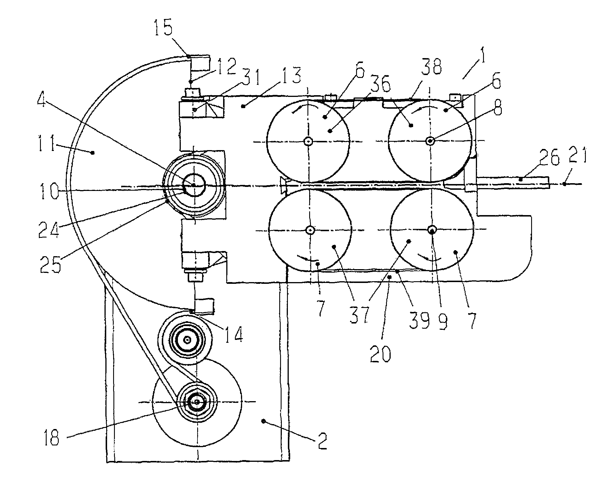
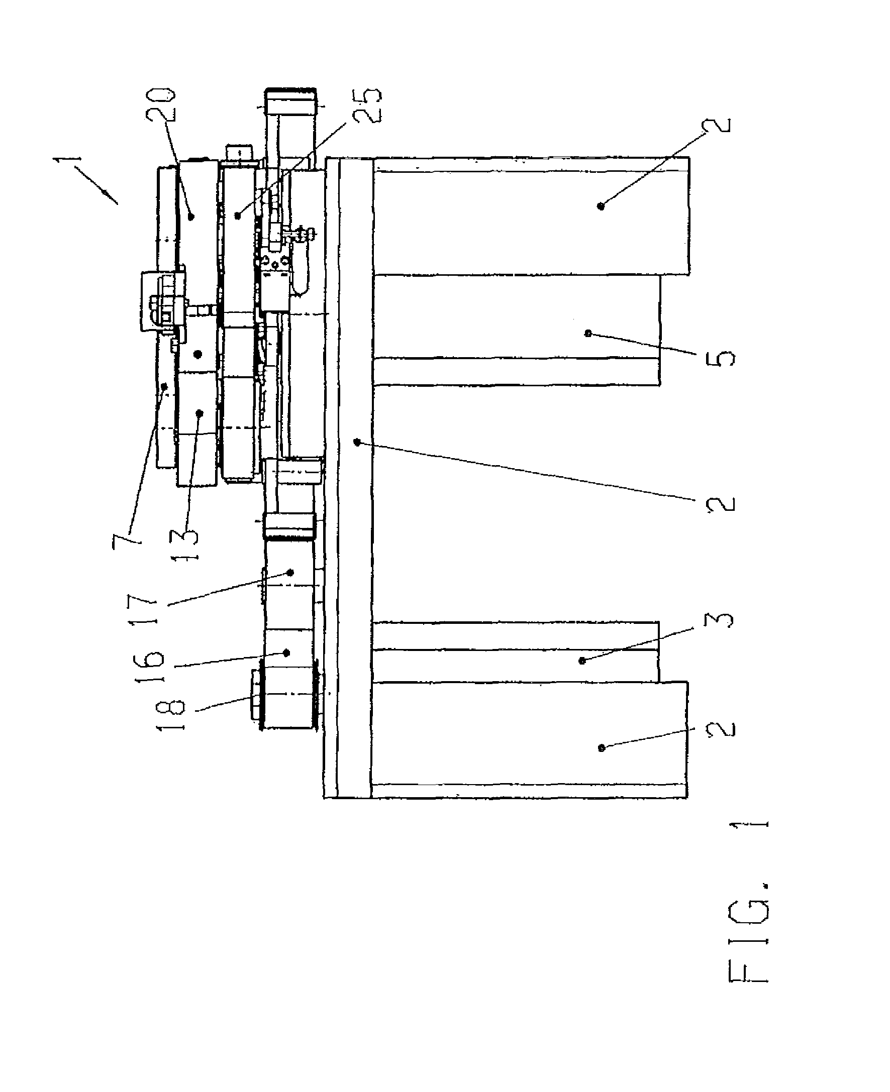
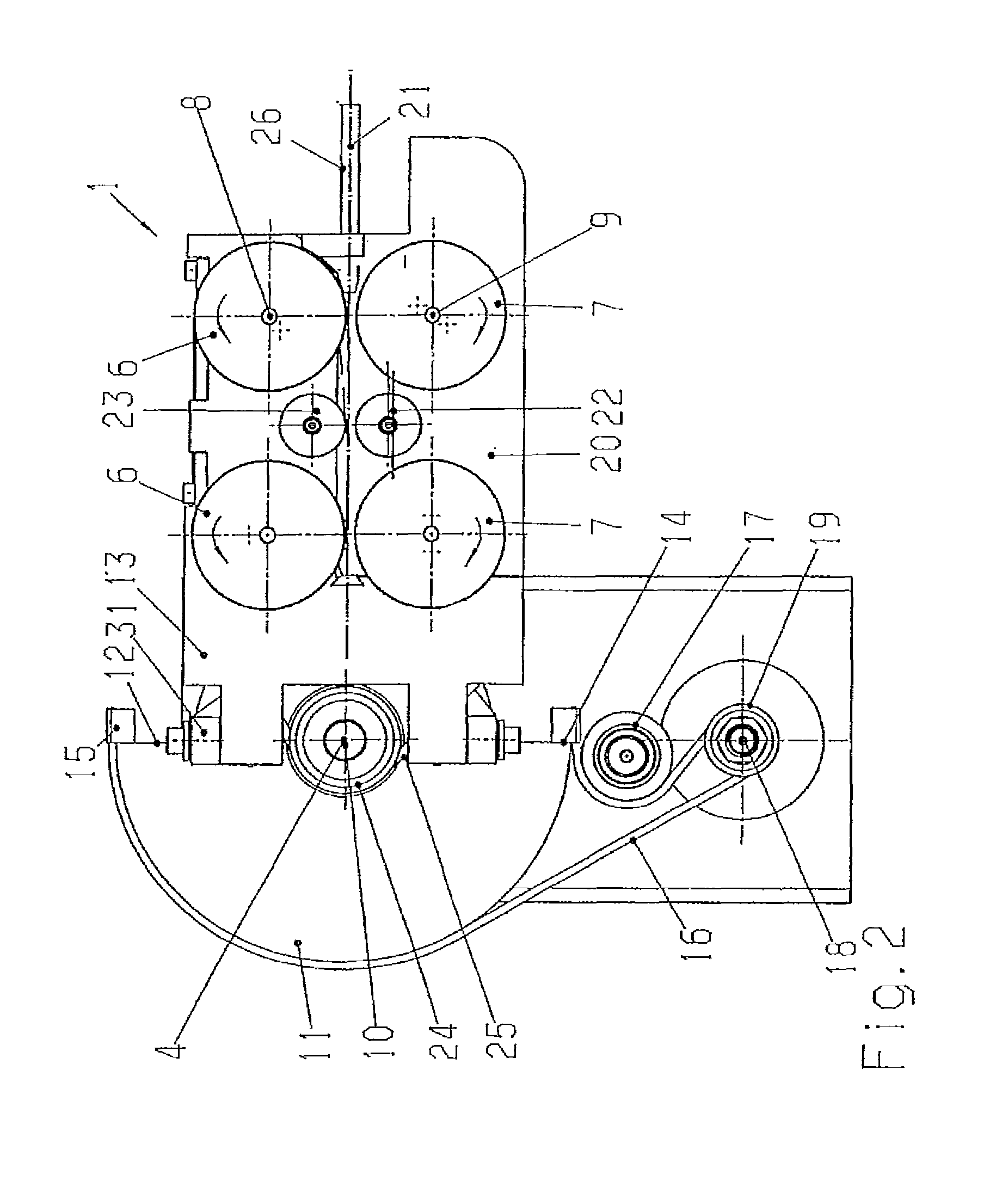
[0029]The cable transport device according to FIGS. 1, 2, 6 and 11 has a pivotably mounted cable transporter 1 for a cable 21 to be drawn in and to be transported, and a first drive means 3 connected in a stationary manner to a base frame 2 and intended for achieving an exactly defined pivot movement of the cable transporter 1 about a pivot axis 4. A second drive means 5 ensures synchronous driving of two cooperating pressure rollers 6 with two cooperating pressure rollers 7, whose axes 8, 9 of rotation are parallel to one another and parallel to the common pivot axis 4. The two pressure rollers 7 are, as shown in FIG. 2, arranged so as to be laterally adjustable. Drive means 3 and 5 may be connected in a stationary manner to base frame 2 by suitable connecting means such as screws 47 and 48.

[0030]According to the invention, the second drive means 5 with its drive axle 10 is connected in a stationary manner to the base frame 2. The drive axle 10 of the second drive means 5 for the p...


PUM


Abstract

A cable transport device having a pivotably mounted cable transporter, a first drive means connected in a stationary manner to a base frame and intended for achieving an exactly defined pivot movement of the cable transporter around a pivot axis and a second drive means for synchronous driving of at least two cooperating pressure rollers. The second drive means with a drive axle for the pressure rollers is connected in a stationary manner to the base frame, and the drive axle of the second drive means coincides with the pivot axis for the cable transporter. In additional versions, the second drive means with a drive axle for the pressure rollers is also connected in a stationary manner to the base frame, and the rollers' axes of rotation are parallel to one another and parallel to a common pitch axis. In these versions, transmission of the drive movement to the toothed belt driving the pressure rollers is effected via a toothed belt which is tensioned symmetrically to the center of rotation of the pivot axis between a first intermediate shaft arranged on a base plate of the cable transporter and a second intermediate shaft fixed to the machine frame, the pitch axis of the cable transporter being identical to the axis of the first intermediate shaft. The cable transport device may be equipped with a guide sleeve that includes a grooved plate and a cover plate that may be replaced for adaptation to different cable diameters and for correction of the cable position.

Description

CROSS REFERENCE TO RELATED APPLICATIONS[0001]This application is a continuation of U.S. patent application Ser. No. 12 / 990,116 which is a 371(c) national-stage entry of PCT International Application No. PCT / IB2009 / 052125 filed on May 20, 2009, which claims the benefit of priority to prior Swiss national application no. 00757 / 08 filed on May 20, 2008 and also claims the benefit of priority, and as a non-provisional of, prior U.S. provisional application No. 61 / 117,189 filed on Nov. 23, 2008; the entire contents of PCT International application no. PCT / IB2009 / 052125 and U.S. patent application Ser. No. 12 / 990,116 are incorporated herein by reference.FIELD OF THE INVENTION[0002]The invention relates to a cable transport device having a pivotably mounted cable transporter for a cable to be drawn in and to be transported, a first drive means connected in a stationary manner to a base frame and intended for achieving an exactly defined pivot movement of the cable transporter about a pivot...

Claims


Application Information

Patent Timeline
Patent Type & Authority Patents(United States)
IPC IPC(8): B65H51/10B65H51/32B65H57/04H01R43/052
CPCB65H51/10B65H51/32B65H57/04H01R43/052B65H2404/1421B65H2701/3911
Inventor SCHUTZ, PETERWORTMANN, THOMAS
Owner SCHLEUNIGER
Why Eureka
Try Eureka