Tiled image based scanning for head position for eye and gaze tracking

a technology of eye and gaze tracking and scanning for head position, which is applied in the field of eye gaze tracking, can solve the problems of inability to provide permanent full spatial resolution image acquisition, high sampling rate of eye tracking applications, and inability to speed up the initial read out of full frame,

Active Publication Date: 2016-10-11
APPLE INC
View PDF10 Cites 3 Cited by
  • Summary
  • Abstract
  • Description
  • Claims
  • Application Information

AI Technical Summary

Benefits of technology

[0027]This enables a faster determination of the region of interest (ROI) for the actual eye or gaze tracking because initially only a part of the sensor area is read out, in contrast to reading out a full frame according to the prior art. Thus, the system does not need to operate with lower frame rates. Rather, the system can operate at a constant frame rate and pick-up speed is increased.
[0048]According to one embodiment, said searching the image data comprises using horizontal or vertical or combined horizontal and vertical binning, skipping, or sub-sampling of the image data of said initially read out part to accelerate search.

Problems solved by technology

Due to limited bandwidth of the camera bus, the frame rate of the system depends on size and spatial resolution of the grabbed image.
However, miscellaneous eye tracking applications require high sampling rates that cannot be provided using permanent full spatial resolution image acquisition.
However, this speed-up does not apply to the initial read out of the full frame.
However, various problems continue to exist.
Moreover, switching between full spatial resolution based image acquisition and ROI based image acquisition causes a delay in camera operation with many common camera models which results in a decreased data rate.
A final issue is that changes in data frame rate complicate the subsequent data analysis due to frame rate dependent parameters.

Method used


Image

  • Tiled image based scanning for head position for eye and gaze tracking
  • Tiled image based scanning for head position for eye and gaze tracking
  • Tiled image based scanning for head position for eye and gaze tracking

Examples


embodiment 1

[0142]2) The embodiment 1), which may or may not include one or more light emitting elements

[0143]3) The embodiment 1-2 where some form of resolution reduction, such as binning or skipping or sub-sampling may or may not be used according to a horizontal or vertical or combined horizontal and vertical pattern to selectively reduce the number of pixels being transmitted or processed

[0144]4) The embodiment 1-3, where the search method tries to substantially locate or identify at least part of at least one said feature within the (sub)set of light sensitive element or ROI defined by a partial readout occurred within a given sampling interval

[0145]5) The embodiment 1-4, where the size and shape of the ROI can be set to constant values

[0146]6) The embodiment 1-5, where the size and shape of the ROI can be dynamically changed at different time periods

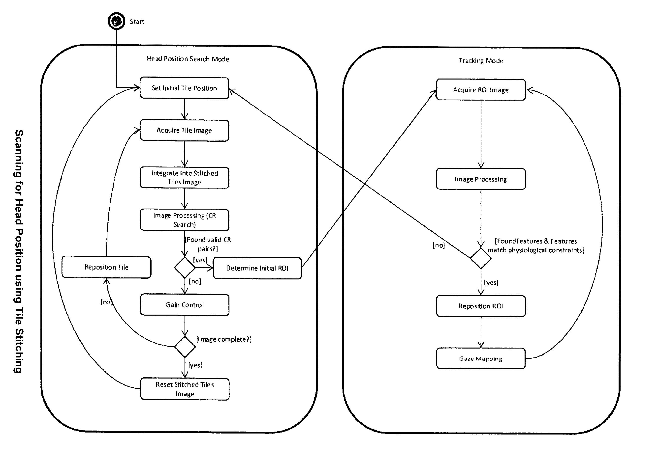
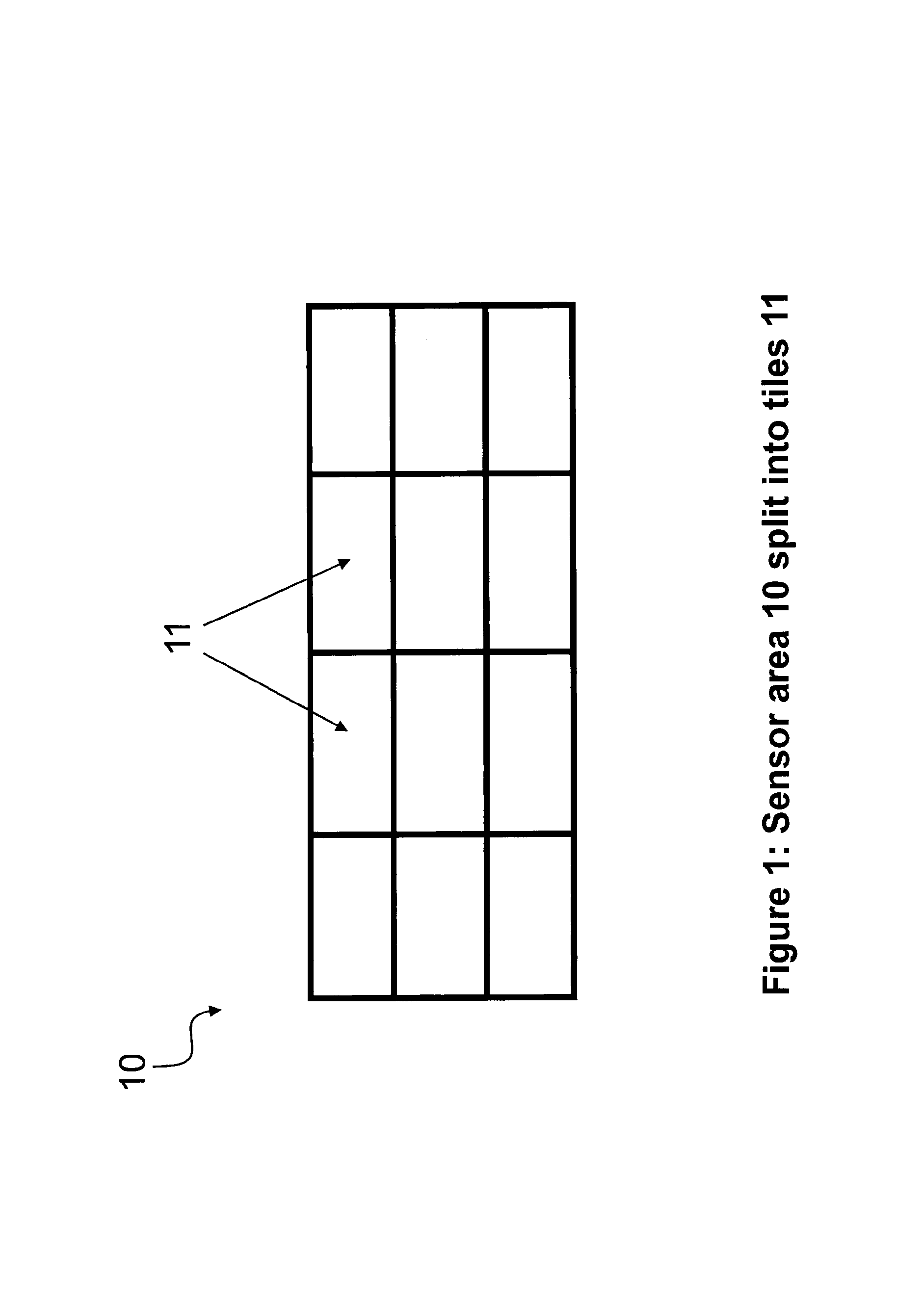
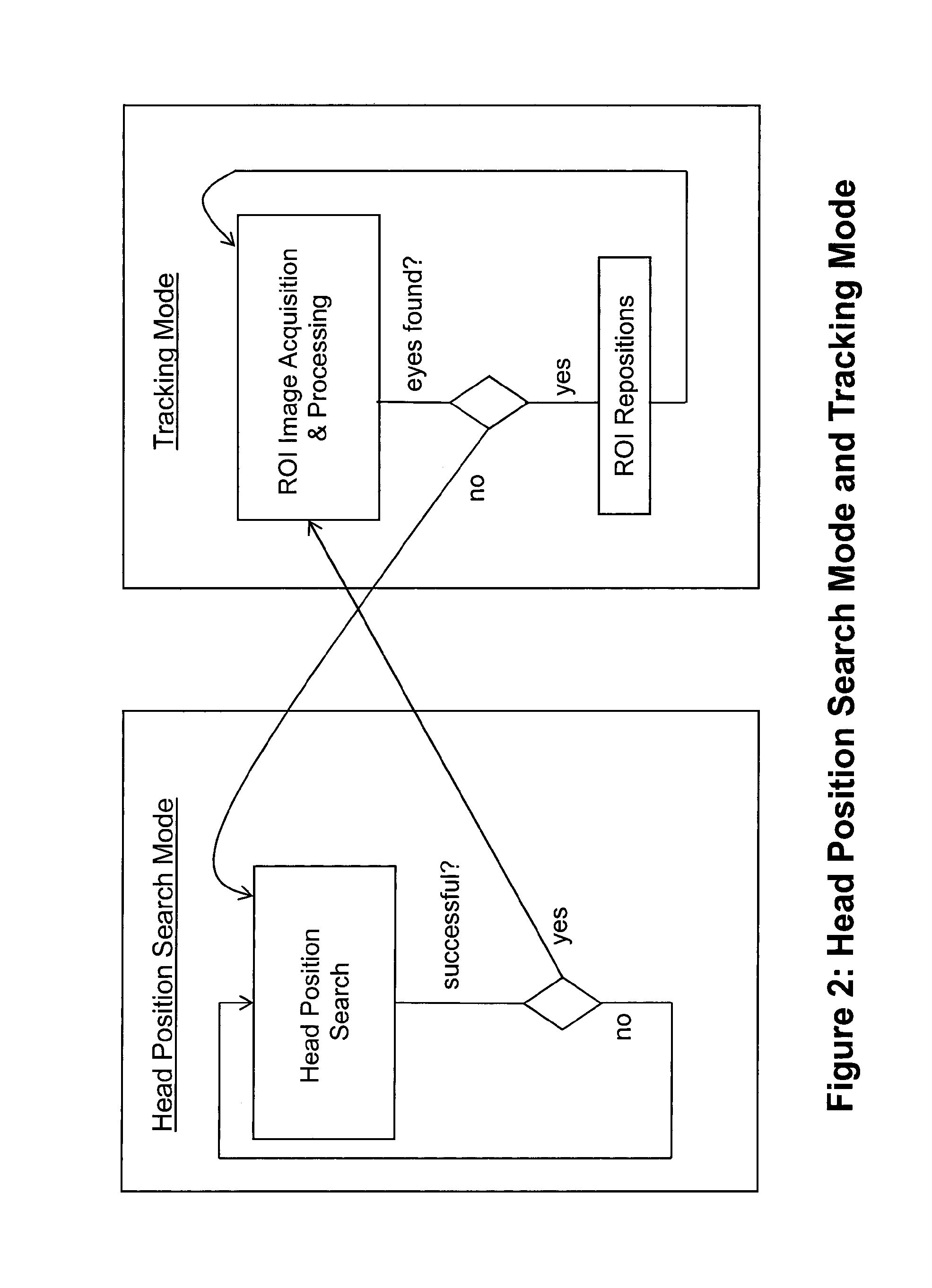
[0147]7) The embodiments 1-6, where the searching method consists in stitching or combining within a processing unit's memory one or more of ...

embodiment 8

[0149]9) The embodiment 8, where physiological and geometrical constraints are applied to features stored in the Feature Accumulator to exclude false positive detections, to reconstruct a feature's complete shape from one or more partial fragments, and to use said together with said model to substantially determine a user's head position and / or orientation and / or one or more eyes position(s) and / or orientations

embodiment 9

[0150]10) The embodiment 9, where time of detection of one or more said features can be used to determine a confidence value to features which may be used to privilege newer features compared to older features from the same area or ROI

[0151]11) The previous embodiments, where time of detection of features can be used to determine movement velocity of one or more heads or one or more eyes and said velocity(ies) can be used to track and / or predict head(s) and eye(s) positions at future time intervals, where said prediction can be used to determine future location(s) of said ROI(s)

[0152]12) The previous embodiments, where the position of one or more ROIs can be defined statically:[0153]a) In the middle of the sensor[0154]b) At a corner of the sensor[0155]c) At a position with a high probability of finding the head position. Probability depends on head position statistics that has been created offline.

[0156]13) The previous embodiments, where the position of one or more ROIs can be defi...


PUM


Abstract

An eye tracking method comprising: capturing image data by an image sensor; determining a region of interest as a subarea or disconnected subareas of said sensor which is to be read out from said sensor to perform an eye tracking based on the read out image data; wherein said determining said region of interest comprises: a) initially reading out only a part of the area of said sensor; b) searching the image data of said initially read out part for one or more features representing the eye position and / or the head position of a subject to be tracked; c) if said search for one or more features has been successful, determining the region of interest based on the location of the successfully searched one or more features, and d) if said search for one or more features has not been successful, reading out a further part of said sensor to perform a search for one or more features representing the eye position and / or the head position based on said further part.

Description

FIELD OF THE INVENTION[0001]This invention is concerned with eye gaze tracking, in particular with increasing the frame rate of camera based remote eye tracking systems using ROI based image acquisition and determining an initial ROI position for eye tracking.BACKGROUND OF THE INVENTION[0002]In current eye tracking systems camera images are processed to determine the position and / or gaze direction of an eye or the eyes. This can be done by detecting features in the image. Features are for example:[0003]Pupils[0004]Corneal Reflexes[0005]For each feature, typically size, contour and position are extracted. Subsequent processing calculates gaze vector and gaze point from these features.[0006]Camera based remote eye trackers provide a large working range for head movement. With a fixed focal length of the camera lens and without joints to change camera orientation, the working range has to be covered completely by the camera sensor.[0007]Due to limited bandwidth of the camera bus, the f...

Claims


Application Information

Patent Timeline
Patent Type & Authority Patents(United States)
IPC IPC(8): G06K9/00A61B3/113G06T7/00
CPCG06K9/0061A61B3/113G06K9/00362G06K9/00604G06K9/00624G06T7/004G06T7/70G06T7/73G06T7/246G06V40/19G06V40/193G06V40/10G06T11/60G06T2207/30201
Inventor RONNECKE, STEFANJABLONSKI, THOMASVILLWOCK, CHRISTIANNISTICO, WALTER
Owner APPLE INC
Why Eureka
Try Eureka