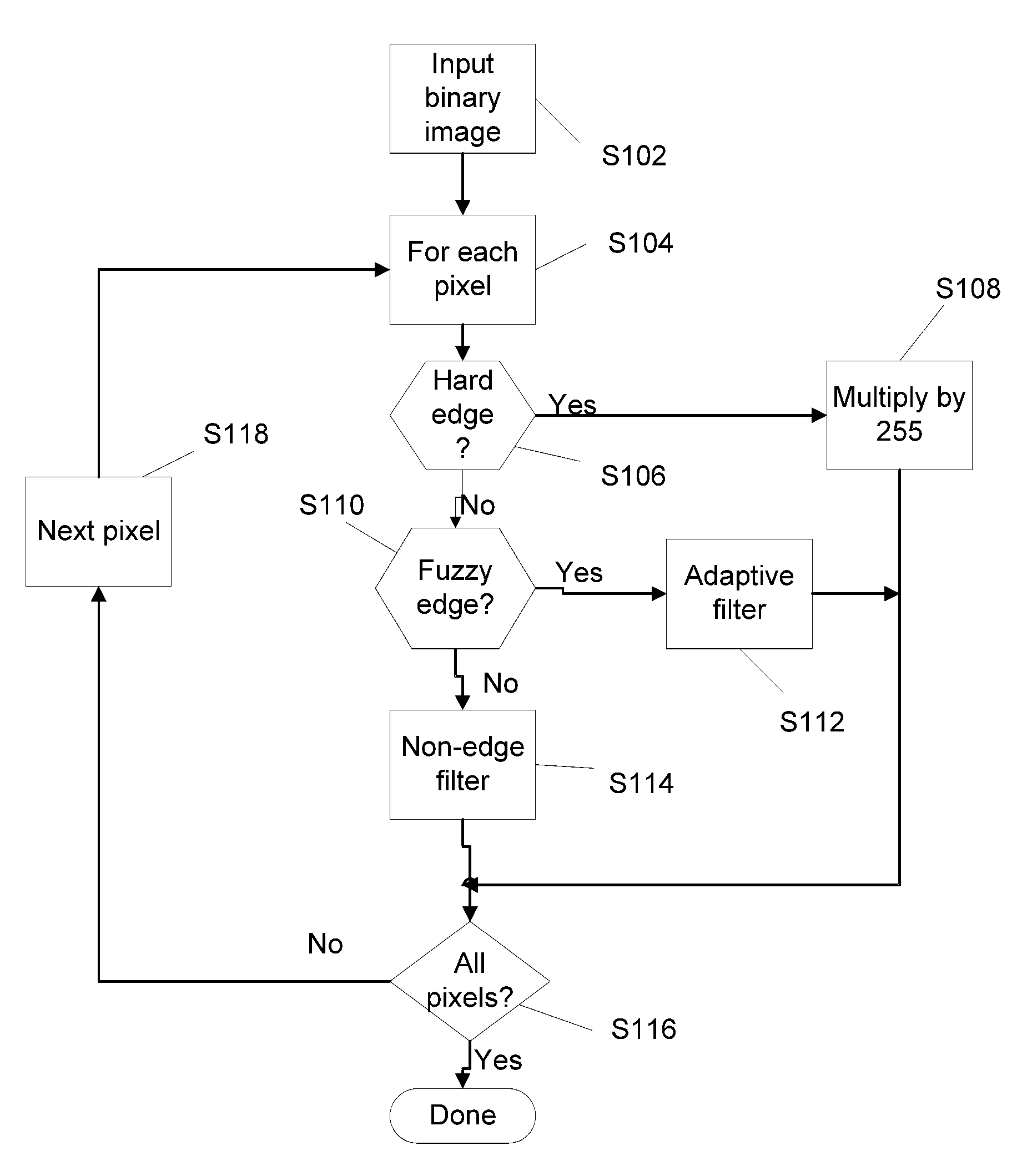
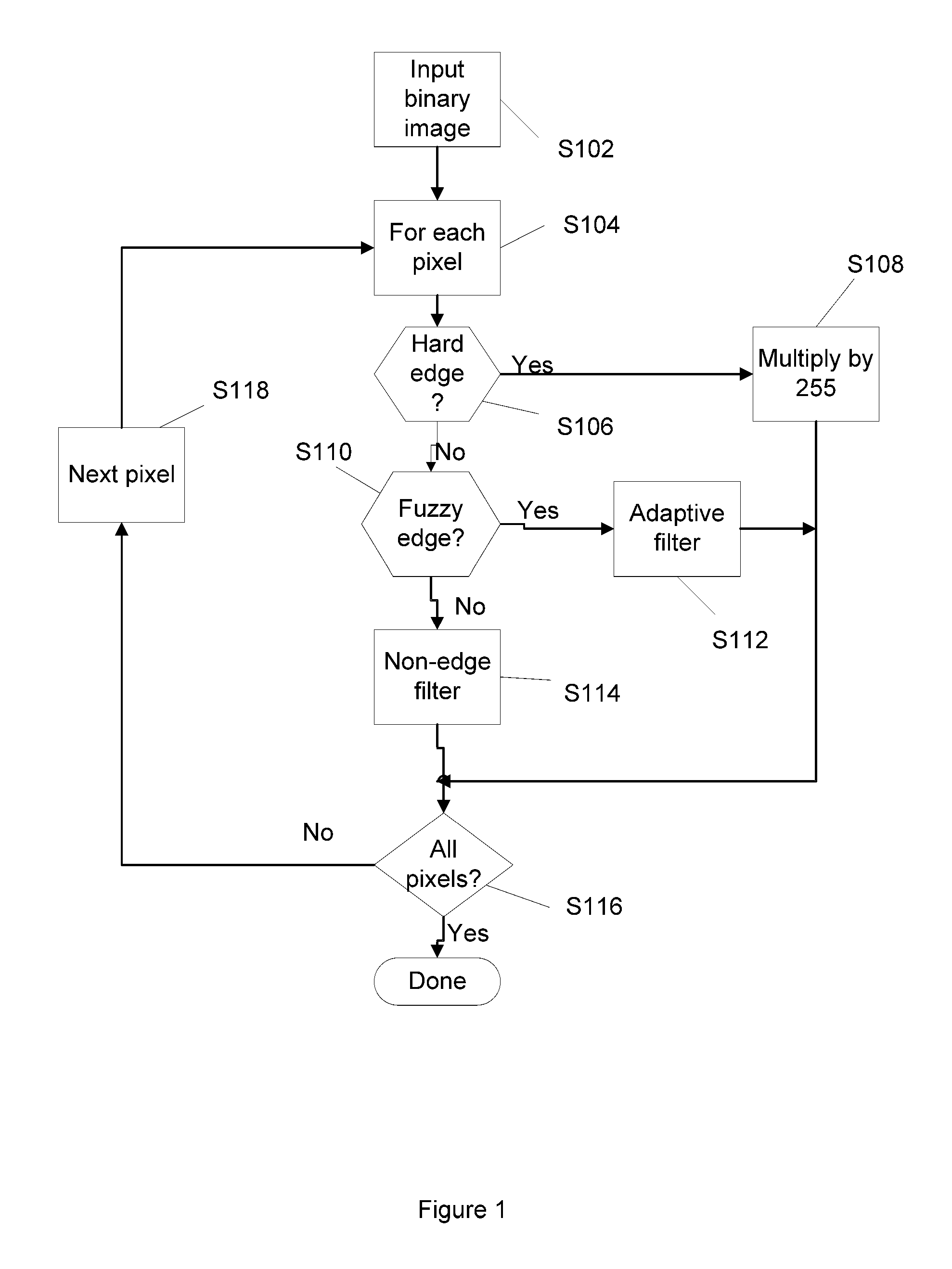
Method for binary to contone conversion with non-solid edge detection
a conversion method and non-solid edge technology, applied in image enhancement, instruments, image data processing, etc., can solve the deleterious effect of smearing sharp edges in original documents, cost constraints and perhaps performance limits of the devices or software that comprise the image path, and the image path is usually one of the more complex and costly components of such digital multi-function devices. , to achieve the effect of reducing hardware and storag
- Summary
- Abstract
- Description
- Claims
- Application Information
AI Technical Summary
Benefits of technology
Problems solved by technology
Method used
Image

Examples
Embodiment Construction
[0030]For a general understanding, reference is made to the drawings. In the drawings, like references have been used throughout to designate identical or equivalent elements. It is also noted that the drawings may not have been drawn to scale and that certain regions may have been purposely drawn disproportionately so that the features and concepts could be properly illustrated.
[0031]In the context of this disclosure, the term “grayscale image” is defined as a digital image with more than 1 bit per pixel (multi-bit depth), having 2n “levels” of intensity wherein n is the number of bits-per-pixel; e.g., 4 bits-per-pixel corresponds to 16 levels of intensity. Grayscale image data may also include “contone” image data or “continuous tone” image data.
[0032]In contrast, the term “binary image” is defined as a digital image with only 1 bit per pixel (single-bit depth). As such, pixels of binary images are limited to only two levels: 0 and 1.
[0033]Grayscale images can be combined with any...
PUM
| Property | Measurement | Unit |
|---|---|---|
| size | aaaaa | aaaaa |
| depth | aaaaa | aaaaa |
| Grayscale | aaaaa | aaaaa |
Abstract
Description
Claims
Application Information
 - R&D
- Intellectual Property
- Life Sciences
- Materials
- Tech Scout
- Unparalleled Data Quality
- Higher Quality Content
- 60% Fewer Hallucinations
Browse by: Latest US Patents, China's latest patents, Technical Efficacy Thesaurus, Application Domain, Technology Topic, Popular Technical Reports.
© 2025 PatSnap. All rights reserved.Legal|Privacy policy|Modern Slavery Act Transparency Statement|Sitemap|About US| Contact US: help@patsnap.com