Catalyst for preparing phosgene and method for preparing phosgene using the same

a catalyst and phosgene technology, applied in the field of phosgene preparation, can solve the problems of reducing the synthesis reaction speed, wasting considerable amount of reaction heat, and reducing the color quality of products, so as to reduce the loss and pulverization of activated carbon, reduce the cost of equipment and utility costs, and reduce the effect of synthesis reaction speed

Active Publication Date: 2016-07-26
WANHUA CHEM GRP CO LTD +1
View PDF9 Cites 0 Cited by
  • Summary
  • Abstract
  • Description
  • Claims
  • Application Information

AI Technical Summary

Benefits of technology

[0010]It is an object of the present invention to provide a catalyst for preparing phosgene and a method of preparing phosgene using said catalyst. The method can lower the radial and axial temperature difference of the reactor effectively, reduce the carbonization and pulverization of the catalyst in the case of high temperature operation, and prolong the life time of the catalyst. Meanwhile, the method can obtain high quality of phosgene and the byproduct steam, reduce the equipment investment cost and the maintenance cost of stable operation, and prolong the safe operation cycle of the apparatus.
[0023]The heat transfer medium of the present invention comprises boiling water or high boiling organics, wherein the high boiling organics comprise carbon tetrachloride, chlorobenzene, ortho-dichlorobenzene, toluene etc., preferably boiling water. Vapor is produced by the phase change of the boiling water or other boiling organics in the shell-side of the fixed bed reactor. Since the heat absorbed by vaporization is much larger than the heat absorbed by temperature rising of liquid, the radial temperature difference of the bed can be reduced, which ensures the heat released in the course of the reaction is rapidly removed, at the same time, the bubbling at the tube wall of the shell-side further reinforces the conduction of the heat produced in the reaction and eliminates the hot spots in the bed.
[0024]When the activated carbon coating / foamed silicon carbide structural catalyst used in the present invention has operated for a long time at high temperature, the active component of the catalyst, i.e., the activated carbon may lose or become pulverized. On the one hand, by introducing the alkali metal salt on the surface of the catalyst, if at high temperature, the alkali metal salt is melted on the surface of the foamed silicon carbide and encloses a part of the catalyst active components, which may decrease the volatilization of the activated carbon, reduce the active sites of the catalyst, adjust the activity of the catalyst and inhibit the reaction speed, thereby control the reaction temperature. On the other hand, the phosgenation reaction is mainly carried out in the pores / channels of surface of the activated carbon catalyst, the heat released by the reaction is partly absorbed by the alkali metal salt and by means of the moving of molten alkali metal salt on the surface of the silicon carbide skeleton, and the absorbed heat would be transferred to the reactor wall, which will increase the radial heat transfer coefficient, and reduce the temperature of the activated carbon surface. We modify the activated carbon coating / foamed silicon carbide structural catalyst by using the alkali metal salt, and thereby obtain the catalyst for preparing phosgene having significantly improved operation stability.
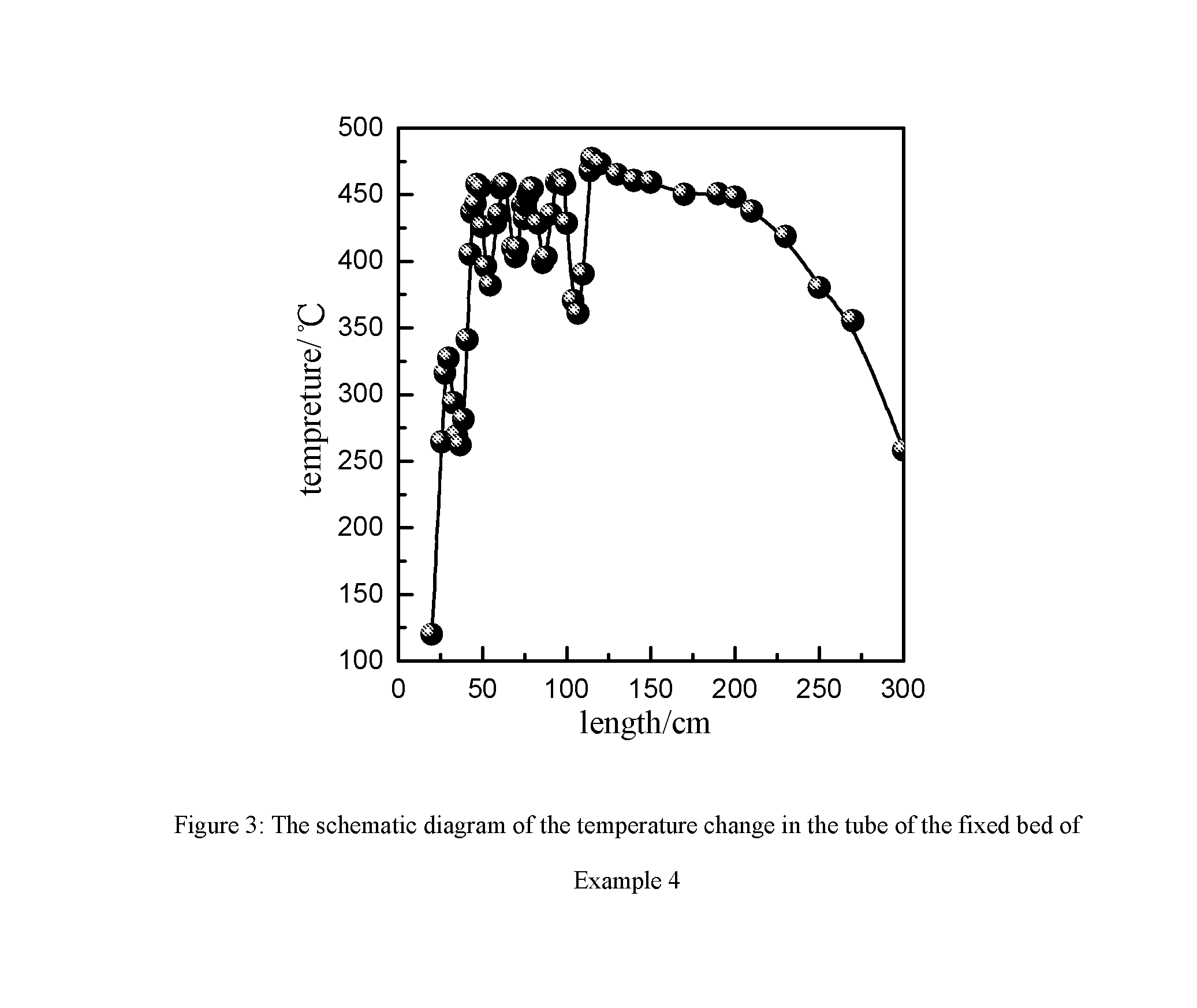
[0026]In the method of the present invention, the temperature of the hot spot of <500° C. in the multi-tubular reactor of the fixed bed is achieved.
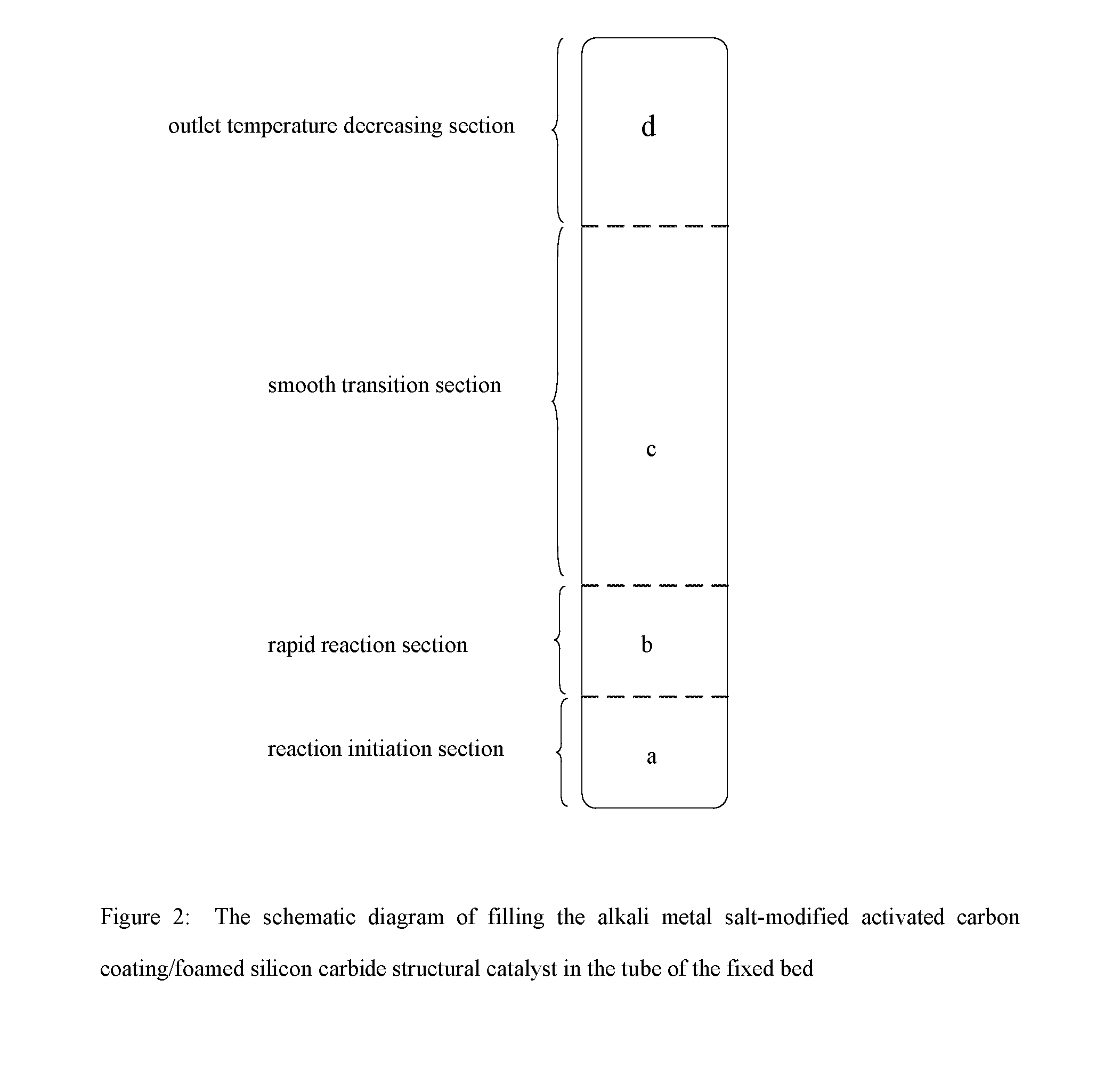
[0029]The method for preparing phosgene using the activated carbon coating / foamed silicon carbide structural catalyst has not been reported so far. The present inventors first researched the use of the above-said catalyst for catalytic synthesis of phosgene in the gas phase. By supporting the activated carbon on the monolithic foamed silicon carbide as the support and adding the alkali metal salt component to the surface of the activated carbon coating / foamed silicon carbide structural catalyst, the loss and pulverization of the activated carbon are reduced, the life time of the catalyst is prolonged, and the radial temperature difference of the tubular (or multi-tubular) reactor of the fixed bed is eliminated. Secondly, by arranging the catalysts having different thickness of the activated carbon coating and different amount of the alkali metal salt in the axial direction of the tubes of the fixed bed, the content of the catalyst in the reaction initiation section is reduced, in order to achieve the purpose of reducing the synthesis reaction speed and of decreasing reaction exothermicity, avoid the formation of the vicious cycle of the reaction speed and the reaction temperature in the entry, and reduce the violent change of the temperature gradient of the bed. In addition, by adjusting the thickness of the activated carbon coating and the amount of the alkali metal salt in the rapid reaction section and the smooth transition section of the tubes, and adjusting the content of the reactive components at the different positions of the axial direction, the axial temperature difference of the catalyst bed is reduced, the synthesis reaction speed of the bed in the axial direction is slowed, the formation of the local hot spots is reduced, and the overall properties of the catalyst in the bed is fully exerted. At the same time, the carbonization, pulverization and loss of the activated carbon component due to the long-term operation at the hot spot temperature of 550˜700° C. in the bed are avoided, and the uneven temperature of the heat transfer medium in the shell-side axial direction and the equipment material waste are avoided. Finally, by mixed loading the foamed silicon carbide catalyst containing the active component, i.e. the activated carbon and the foamed silicon carbide skeleton in the outlet temperature decreasing section, not only the temperature of the reactor outlet is lowered to prevent phosgene from decomposing, but also the content of free chlorine at the exhaust gas outlet is reduced, such that the content of free chlorine is up to standard after the exhaust gas is further reacted in the protective column. Since the temperature during the whole reaction is low, the formation of carbon tetrachloride from the reaction of the activated carbon and chlorine gas is prevented, such that the content of carbon tetrachloride in the exhaust gas is reduced and the quality of the phosgene product is improved.

Problems solved by technology

For example, for phosgene used to prepare polycarbonates, the presence of free chlorine has problems such as adverse effects on water washing and severe equipment corrosion, thus at most 50 ppm free chlorine is allowed to be contained in said phosgene; and the presence of carbon tetrachloride impurity has problems such as adverse effects in the color quality of product, thus at most 50 ppm carbon tetrachloride is allowed to be contained in said phosgene.
As such, the considerable amount of reaction heat is wasted, and the high equipment and utility cost is additionally needed.
The above-said reaction can be rapidly conducted under the action of a catalyst at ambient temperature, and releases a large amount of heat.
If the reaction speed is further accelerated, more heat will be released, which leads to a vicious cycle.
The traditional filling method not only fails to lower the reaction rate and the rate of heat release near the feed inlet to prevent temperature runaway happening, but also it may decrease the effective utilization of the active catalyst.
Thus, the fixed bed reactor would have a big change in the axial temperature gradient, resulting in the catalytic performance of the overall catalyst bed decreased, the uneven temperature of the heat transfer medium moved upwardly in the shell-side axial direction and the equipment material waste.
And at such a high reaction temperature, long-term running will result in carbonization, pulverization of the activated carbon catalyst, so that eventually most activated carbon catalyst loses.
Since there are a large number of irregular open pores and closed pores in the interior of the activated carbon catalyst, the heat transfer effect of the activated carbon is very poor.
Further, the burning of the catalyst would lead to lowering of the pressure drop across the bed and make more material enter into the area where the lowering of the pressure drop took place, and therefore the reaction would be further out of control, which might result in a serious safety accident.
However, the steam by-produced in the process has low quality, and the lifetime of the activated carbon catalyst is short.
This is because the activated carbon catalyst has high heat resistance, such that the overall reaction bed has high temperature and heat can not be removed.
Thus, if the problem of high temperature gradient in the catalyst bed, especially the problem of the high radial temperature gradient, can not be solved, the heat produced in the reaction will be difficult to be comprehensively utilized.
If the heat transfer medium is water, it needs to solve the safety problem of leakage of the heat transfer medium to the reaction region due to the local high temperature corrosion damage, otherwise, this will affect stable operation of the apparatus adversely.
If the heat transfer medium is organics, the heat transfer effect is poor, and it needs to solve the problems such as carbonization of the heat transfer medium in the shell-side at high temperature to cause clogging, difficulty of cleaning the resulting carbides and so on, otherwise this will affect stable operation of the apparatus.
As described above, the prior art methods for preparing phosgene by the catalytic reaction of carbon monoxide and chlorine gas mainly have the problems as follows: serious carbonization and pulverization of the existing activated carbon catalysts, short life time, large radial and axial temperature difference, low quality of phosgene and the by-produced steam, failure to long-term stable operation, high maintenance cost, poor safety etc.

Method used

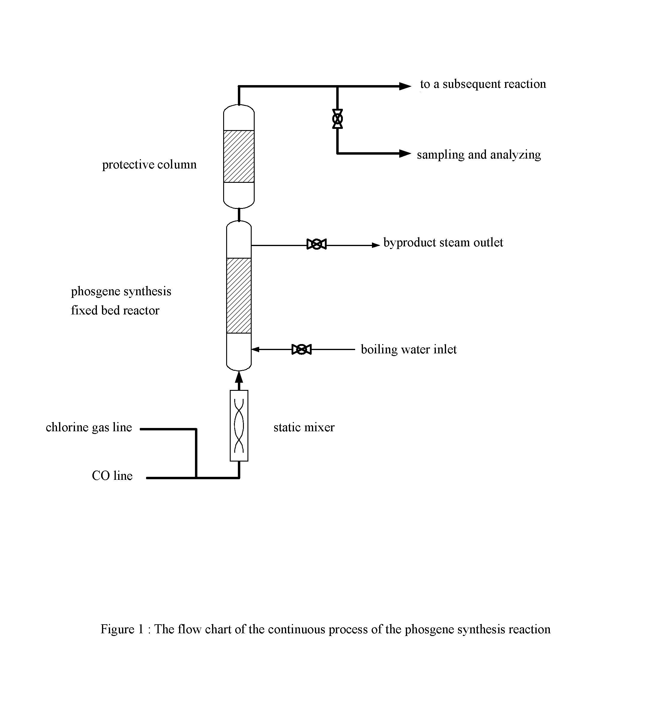

Image

  • Catalyst for preparing phosgene and method for preparing phosgene using the same
  • Catalyst for preparing phosgene and method for preparing phosgene using the same
  • Catalyst for preparing phosgene and method for preparing phosgene using the same

Examples


example 1

[0060](1) The foamed silicon carbide ceramic having the average pore size of 1 mm is immersed in 3 mol / L of NaOH solution for 10 minutes, and washed with water and then baked under air atmosphere of 120° C. for 3 hours;[0061](2) A suspension is prepared according to the proportion of phenolic resin:activated carbon:curing agent (hexamethylene tetramine):ethyl alcohol=100:50:2:100 on a weight basis, and a slurry is obtained by ball-milling said suspension for 1 hour;[0062](3) The foamed silicon carbide ceramic after washing and drying is immersed in the above-said slurry of the activated carbon for 5 minutes, and then is taken out and blown away the excess slurry from it using compressed air, and baking it under air atmosphere of 100° C.;[0063](4) Step (3) is repeated by using the baked product from the above step until the loading of the coating of the activated carbon reaches 200 g / L;[0064](5) The sample is heated to 700° C. at the speed of 2° C. / minute under nitrogen atmosphere an...

example 2

[0067](1) The activated carbon coating / foamed silicon carbide structural catalyst prepared by Example 1 is immersed in 1.5 mol / L of aqueous sodium chloride (NaCl) solution for 4 hours, and washed with water and then baked under air atmosphere of 100° C.;[0068](2) Step (1) is repeated using the baked sample until the loading of NaCl reaches 50 g / L;[0069](3) The baked sample is calcined at 400° C. for 2 hours under the protection of nitrogen atmosphere to obtain sodium chloride (NaCl)-modified activated carbon coating / foamed silicon carbide structural catalyst having sodium chloride content of 30 g / L.

[0070]As an another example, steps (1)˜(3) are repeated, but the activated carbon coating / foamed silicon carbide structural catalyst is immersed in 0.8 mol / L of NaCl aqueous solution for 2 hours to prepare the baked catalyst having the loading of sodium chloride of 0.6 g / L. The sample is calcined at 400° C. under the protection nitrogen atmosphere for 2 hours to obtain sodium chloride (Na...

example 3

[0073](1) The activated carbon coating / foamed silicon carbide structural catalyst prepared by Example 1 is immersed in 1.5 mol / L of aqueous potassium chloride (KCl) solution for 2 hours, and washed with water and then baked under air atmosphere of 100° C.;[0074](2) Step (1) is repeated using the baked sample until the loading of KCl reaches 20 g / L;[0075](3) The baked sample is calcined at 500° C. for 1 hours under the protection of nitrogen atmosphere to obtain potassium chloride (KCl)-modified activated carbon coating / foamed silicon carbide structural catalyst having potassium chloride content of 15 g / L.

[0076]As an another example, steps (1)˜(3) are repeated, but the activated carbon coating / foamed silicon carbide structural catalyst is immersed in 1.5 mol / L of aqueous KCl solution for 4 hours to prepare the baked catalyst having the loading of potassium chloride of 30 g / L. The sample is calcined at 400° C. under the protection of nitrogen atmosphere for 2 hours to obtain potassium...


PUM

PropertyMeasurementUnit
thicknessaaaaaaaaaa
thicknessaaaaaaaaaa
thicknessaaaaaaaaaa

Abstract

The present invention relates to a catalyst for preparing phosgene and a method for preparing phosgene using the catalyst. Said method comprises: modifying the surface of an activated carbon coating / foamed silicon carbide structural catalyst using an alkali metal salt; filling the catalysts having different thickness of the activated carbon coating and different amount of the alkali metal salt in different sections in the axial direction of the multi-tubular reactor of the fixed bed, and preparing phosgene using Cl2 and CO. The radial and axial temperature difference of the catalyst bed is lowered by using the alkali metal salt-modified activated carbon coating / foamed silicon carbide structural catalyst and by segmental filling, so that high temperature of tube wall is obtained in the case of a larger tube diameter, and high quality of steam is obtained stably.

Description

FIELD OF THE INVENTION[0001]The present invention relates to the field of preparing phosgene, and more particularly to a catalyst for preparing phosgene and a method for preparing phosgene using the same.BACKGROUND OF THE INVENTION[0002]Phosgene is one of the important organic intermediates, and can be used in the fields of agrichemicals, medicines, engineering plastics, polyurethanes, military uses etc. It is particularly the important raw material for producing isocyanates and polycarbonates.[0003]Phosgene is synthesized by using carbon monoxide and chlorine gas as the raw materials, activated carbon as catalyst in the industry. The reaction equation is showed as formula (1):CO+Cl2=COCl2ΔH=−31.6 kcal / mol  (1)High quality of phosgene is primarily provided for high-end product use. For example, for phosgene used to prepare polycarbonates, the presence of free chlorine has problems such as adverse effects on water washing and severe equipment corrosion, thus at most 50 ppm free chlor...

Claims


Application Information

Patent Timeline
Patent Type & Authority Patents(United States)
IPC IPC(8): C07C51/58B01J37/02B01J35/02B01J35/00B01J21/18B01J27/224B01J37/08C01B31/28C01B32/80
CPCC01B31/28B01J21/18B01J27/224B01J35/0006B01J35/023B01J37/0236B01J37/08B01J23/04B01J37/084B01J37/24B01J37/0219B01J27/10B01J35/04B01J31/06C01B32/80
Inventor CHEN, BINLUO, WUXIYAO, YUSHAO, LIANGFENGWANG, LEIZHANG, HONGKEHUA, WEIQI
Owner WANHUA CHEM GRP CO LTD
Why Eureka
Try Eureka