Liquid crystal display device and useful liquid crystal composition
a display device and liquid crystal technology, applied in liquid crystal compositions, instruments, chemistry apparatuses and processes, etc., can solve the problems of slow response speed, unsatisfactory response speed and viewing angle characteristics of liquid crystal tvs, and inability to adjust the viewing angle, etc., to improve the response speed, increase the amount of light transmission, and improve the effect of response speed
- Summary
- Abstract
- Description
- Claims
- Application Information
AI Technical Summary
Benefits of technology
Problems solved by technology
Method used
Image
Examples
example 1
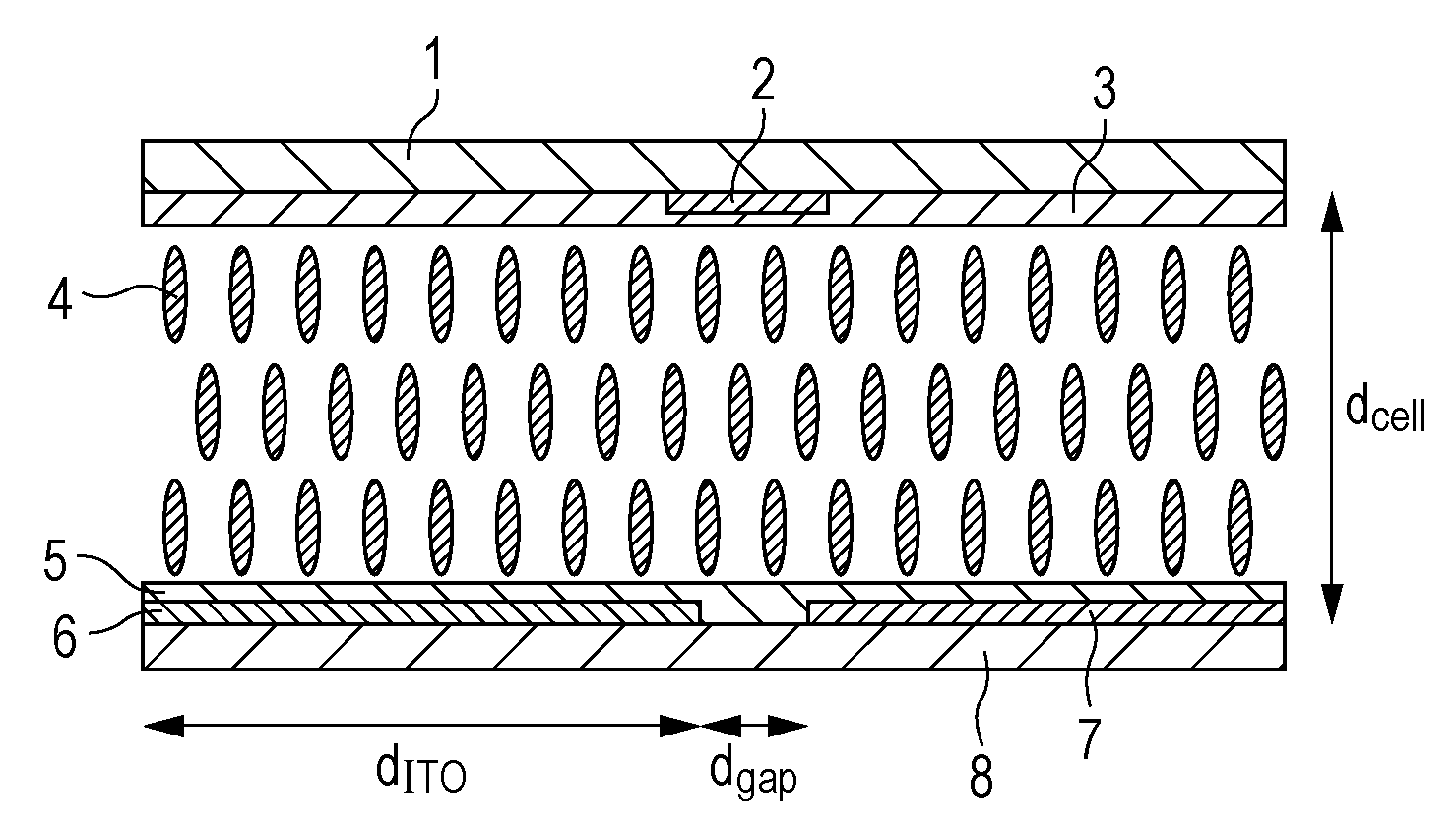
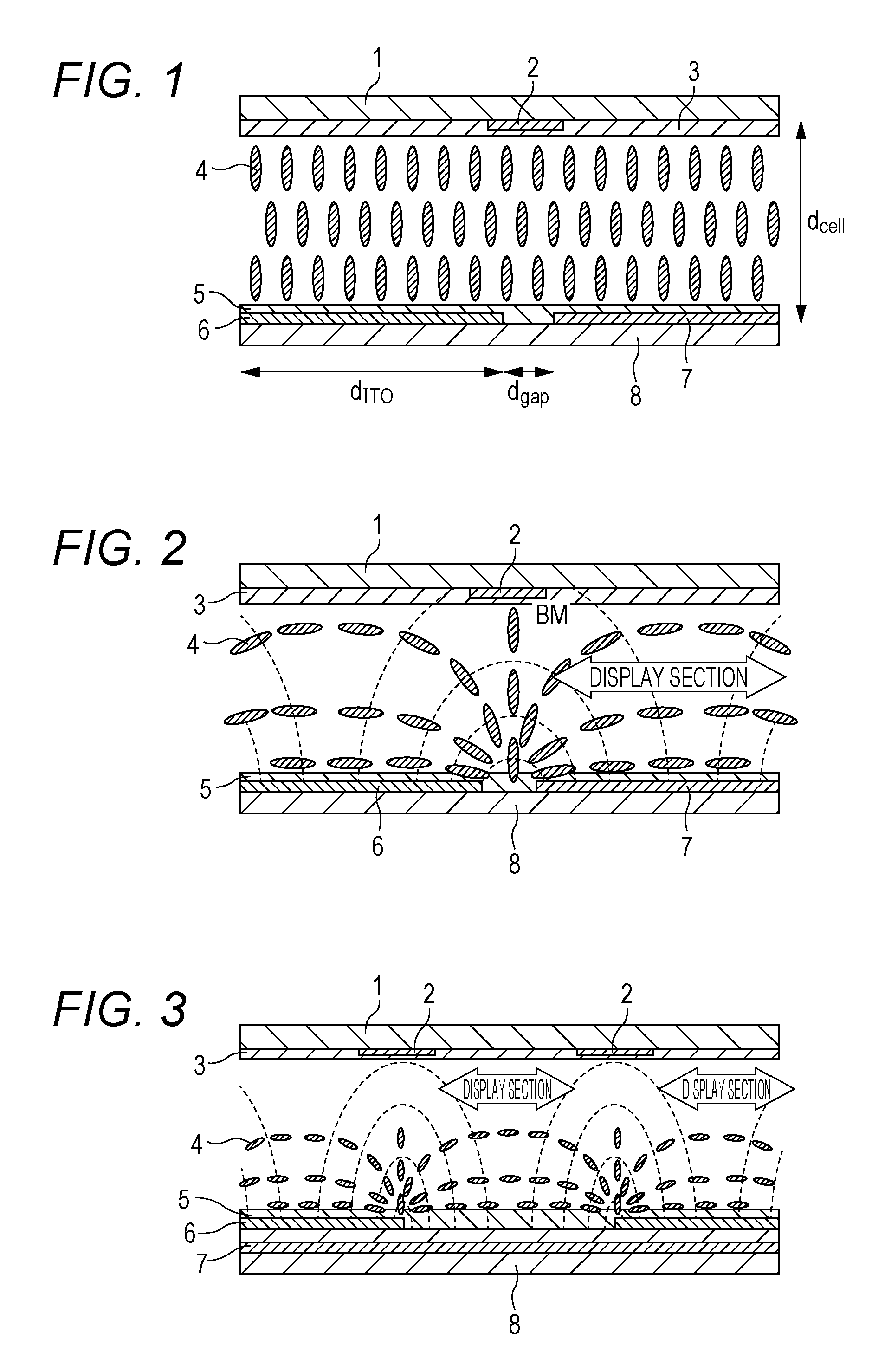
[0095]An electrode structure such as illustrated in FIG. 4 was produced on a second substrate, and a first substrate having no electrode structure provided thereon was used. An alignment film of vertical alignment was formed on each of the respective surfaces that faced each other. The liquid crystals having negative dielectric anisotropy indicated as Example 1 in Table 1 were interposed between the first substrate and the second substrate, and thus a liquid crystal display device was produced (cell thickness: 4.0 μm, alignment film: SE-5300).
example 2
[0098]An electrode structure such as illustrated in FIG. 4 was produced on a second substrate, and a first substrate having no electrode structure provided thereon was used. An alignment film of vertical alignment was formed on each of the other sides of the respective surfaces that faced each other, and an alignment film of horizontal orientation was formed on each of the reverse sides. The liquid crystals having negative dielectric anisotropy indicated as Example 2 in Table 1 were interposed between the first substrate and the second substrate, and thus a liquid crystal display device was produced (cell thickness: 4.0 μm, alignment films: SE-5300, AL-1051). The liquid crystal display device realized a higher response speed, a larger amount of light transmission, a reduction in light leakage caused by external pressure, a wider viewing angle, and a higher contrast ratio, as compared with a conventional VA liquid crystal display device in which the same liquid crystals having negati...
example 3
[0099]An electrode structure such as illustrated in FIG. 4 was produced on a second substrate, and a first substrate having no electrode structure provided thereon was used. An alignment film of vertical alignment was formed on each of the respective surfaces that faced each other. The liquid crystals having negative dielectric anisotropy indicated as Example 3 in Table 1 and 0.3% by mass of 2-methylacrylic acid 4′-{2-[4-(2-acryloyloxyethyl)phenoxycarbonyl]ethyl}biphenyl-4-yl ester were interposed between the first substrate and the second substrate, and thus a liquid crystal display device was produced (cell thickness: 4.0 μm, alignment film: SE-5300). While a driving voltage was applied between the electrodes, ultraviolet radiation was irradiated for 600 seconds (3.0 J / cm2), and thus a polymerization treatment was carried out.
[0100]The liquid crystal display device realized a higher response speed, a larger amount of light transmission, a reduction in light leakage caused by exter...
PUM
| Property | Measurement | Unit |
|---|---|---|
| viscosity | aaaaa | aaaaa |
| tilt angle | aaaaa | aaaaa |
| tilt angle | aaaaa | aaaaa |
Abstract
Description
Claims
Application Information
 - R&D
- Intellectual Property
- Life Sciences
- Materials
- Tech Scout
- Unparalleled Data Quality
- Higher Quality Content
- 60% Fewer Hallucinations
Browse by: Latest US Patents, China's latest patents, Technical Efficacy Thesaurus, Application Domain, Technology Topic, Popular Technical Reports.
© 2025 PatSnap. All rights reserved.Legal|Privacy policy|Modern Slavery Act Transparency Statement|Sitemap|About US| Contact US: help@patsnap.com


