Method for the open-loop control and closed-loop control of an internal combustion engine

Active Publication Date: 2016-05-03
ROLLS ROYCE SOLUTIONS GMBH
View PDF45 Cites 2 Cited by
  • Summary
  • Abstract
  • Description
  • Claims
  • Application Information

AI Technical Summary

Benefits of technology

The patent text describes a system that controls the pressure of a rail to improve reliability and reduce emissions. The system includes a pressure control valve and a closed-loop control system. If there is a failure in the pressure sensor, the system automatically increases the pressure in the rail to prevent damage. This is done using a high-pressure pump that pumps more than necessary, which is redirected to the tank by the pressure control valve. The system uses the same setpoint value for both the pressure control valve and the closed-loop control system, ensuring consistent operation. The small deviation between the actual and set pressure allows for high engine output in emergency operating modes and minimizes emissions.

Problems solved by technology

In practice, the case can arise that after a failure of the rail pressure sensor, the rail pressure rises.
However, since the pressure control valve at a constant setpoint value redirects a greater pressure control valve volume flow into the tank with increasing rail pressure, the pressure rise in the rail is counteracted.

Method used


Image

  • Method for the open-loop control and closed-loop control of an internal combustion engine
  • Method for the open-loop control and closed-loop control of an internal combustion engine
  • Method for the open-loop control and closed-loop control of an internal combustion engine

Examples


Embodiment Construction

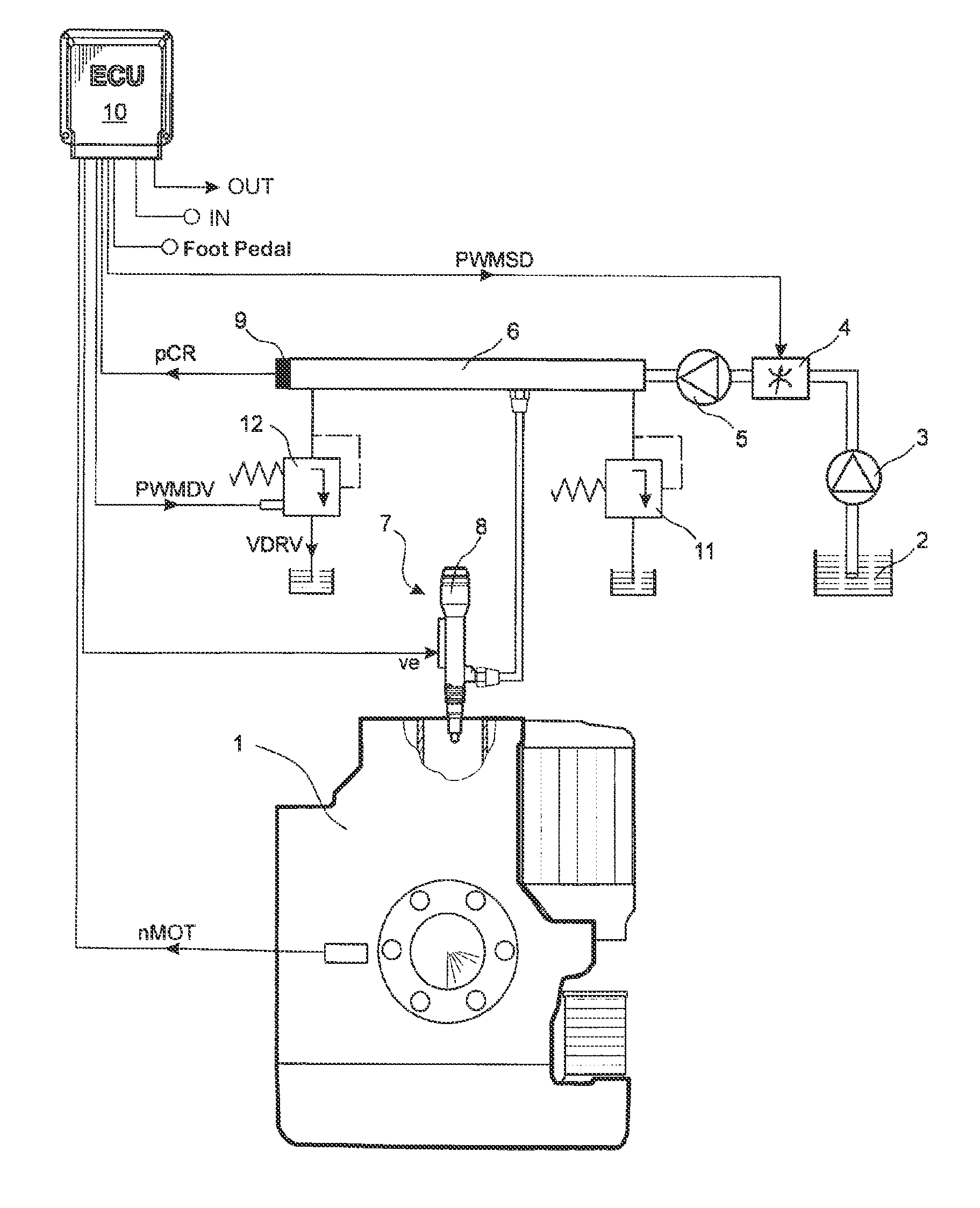
[0020]FIG. 1 shows a system diagram of an electronically controlled internal combustion engine 1 with a common rail system. The common rail system comprises the following mechanical components: a low-pressure pump 3 for pumping fuel from a fuel tank 2, a variable suction throttle 4 on the low-pressure side for controlling the fuel volume flow flowing through the lines, a high-pressure pump 5 for pumping the fuel at increased pressure, a rail 6 for storing the fuel, and injectors 7 for injecting the fuel into the combustion chambers of the internal combustion engine 1. Optionally, the common rail system can also be realized with individual accumulators, in which case an individual accumulator 8 is integrated, for example, in the injector 7 as an additional buffer volume. To protect against an impermissibly high pressure level in the rail 6, a passive pressure control valve 11 is provided, which, in its open state, redirects the fuel from the rail 6 into the fuel tank 2. An electrical...


PUM


Abstract

The invention relates to a method for the open-loop control and the closed-loop control of an internal combustion engine (1), the rail pressure (pCR) being controlled in the normal operating state in a closed loop control mode via an intake throttle (4) on the lower pressure side as the first pressure control member in a rail pressure control loop and at the same time a rail pressure disturbance variable being applied to the rail pressure (pCR) via a pressure control valve (12) on the high pressure side as the second pressure control member. For this purpose, a pressure control valve volume flow (VDRV) is redirected from the rail (6) to a fuel tank (2) via the pressure control valve (12) on the high pressure side, and an emergency operation mode is activated once a defective rail pressure sensor (9) is detected, in which emergency operation the pressure control valve (12) on the high pressure side and the intake throttle (4) on the low pressure side are actuated depending on the same set point value.

Description

[0001]The present application is a 371 of International application PCT / EP2010 / 006381, filed Oct. 19, 2010, which claims priority of DE 10 2009 050 467.2, filed Oct. 23, 2009, the priority of these applications is hereby claimed and these applications are incorporated herein by reference.BACKGROUND OF THE INVENTION[0002]The invention concerns a method for the open-loop and closed-loop control of an internal combustion engine, in which, during normal operation, the rail pressure is automatically controlled in a closed-loop rail pressure control system by a suction throttle on the low-pressure side as a first pressure regulator, and, at the same time, the rail pressure is acted upon with a rail pressure disturbance variable by means of a pressure control valve on the high-pressure side as a second pressure regulator by virtue of the fact that a pressure control valve volume flow is redirected from the rail into a fuel tank by the pressure control valve on the high-pressure side.[0003]...

Claims


Application Information

Patent Timeline
IPC IPC(8): F02D41/38F02M63/02F02D41/02F02D41/22F02D41/14F02D41/20
CPCF02D41/3863F02D41/222F02D41/3854F02M63/025F02D41/1401F02D2041/1411F02D2041/2027F02D2041/223F02D2041/227F02D2250/31
Inventor DOLKER, ARMIN
Owner ROLLS ROYCE SOLUTIONS GMBH
Why Eureka
Try Eureka