Field discharge resistor unit and synchronous motor including same

Active Publication Date: 2019-07-18
HYUNDAI ELECTRIC & ENERGY SYST CO LTD
View PDF0 Cites 0 Cited by
  • Summary
  • Abstract
  • Description
  • Claims
  • Application Information

AI Technical Summary

Benefits of technology

This patent aims to improve the operational reliability of a synchronous motor by securing its thermal stability and reducing thermal damage. The patent suggests adjusting the resistance value and thermal capacity by changing the number and shapes of conductor disks, which can lead to better performance of the motor.

Problems solved by technology

However, the field discharge resistor 10 of the related art may be vulnerable to cooling when being started, and it is highly likely that thermal damage may occur in insulation, which may degrade operational reliability.
Also, the wound coil type field discharge resistor in the related art is configured such that the wound coil is coated with the insulating material 12, and thus, it may not be easy to adjust a resistance value and heat capacity.

Method used


Image

  • Field discharge resistor unit and synchronous motor including same
  • Field discharge resistor unit and synchronous motor including same
  • Field discharge resistor unit and synchronous motor including same

Examples


Embodiment Construction

[0028]Terms used in the specification are used to describe a certain exemplary embodiment, and are not intended to limit the present invention. Also, a singular term includes a plural form unless otherwise indicated.

[0029]Hereinafter, embodiments of the present disclosure will be described with reference to the accompanied drawings.

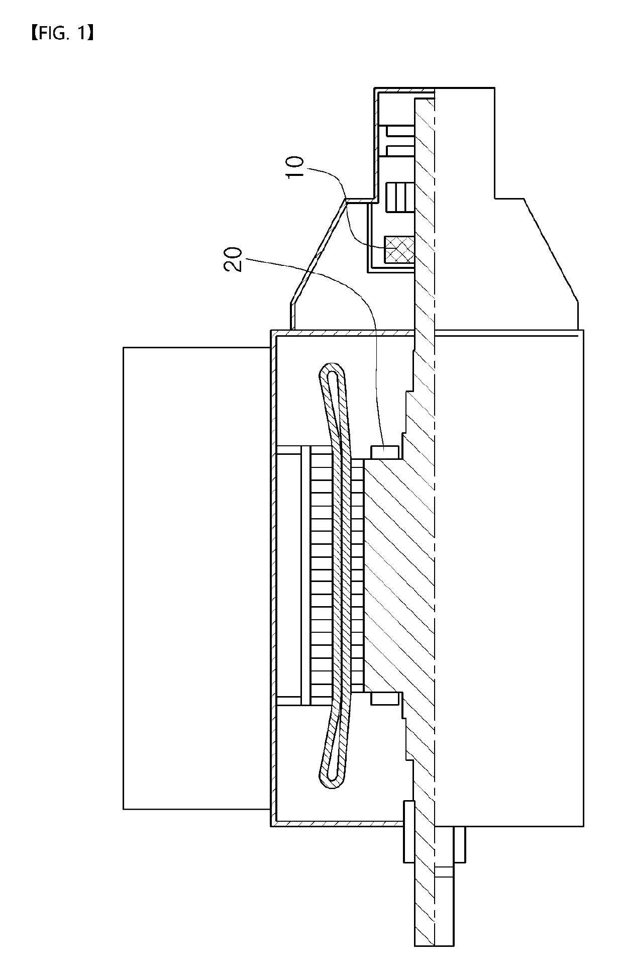
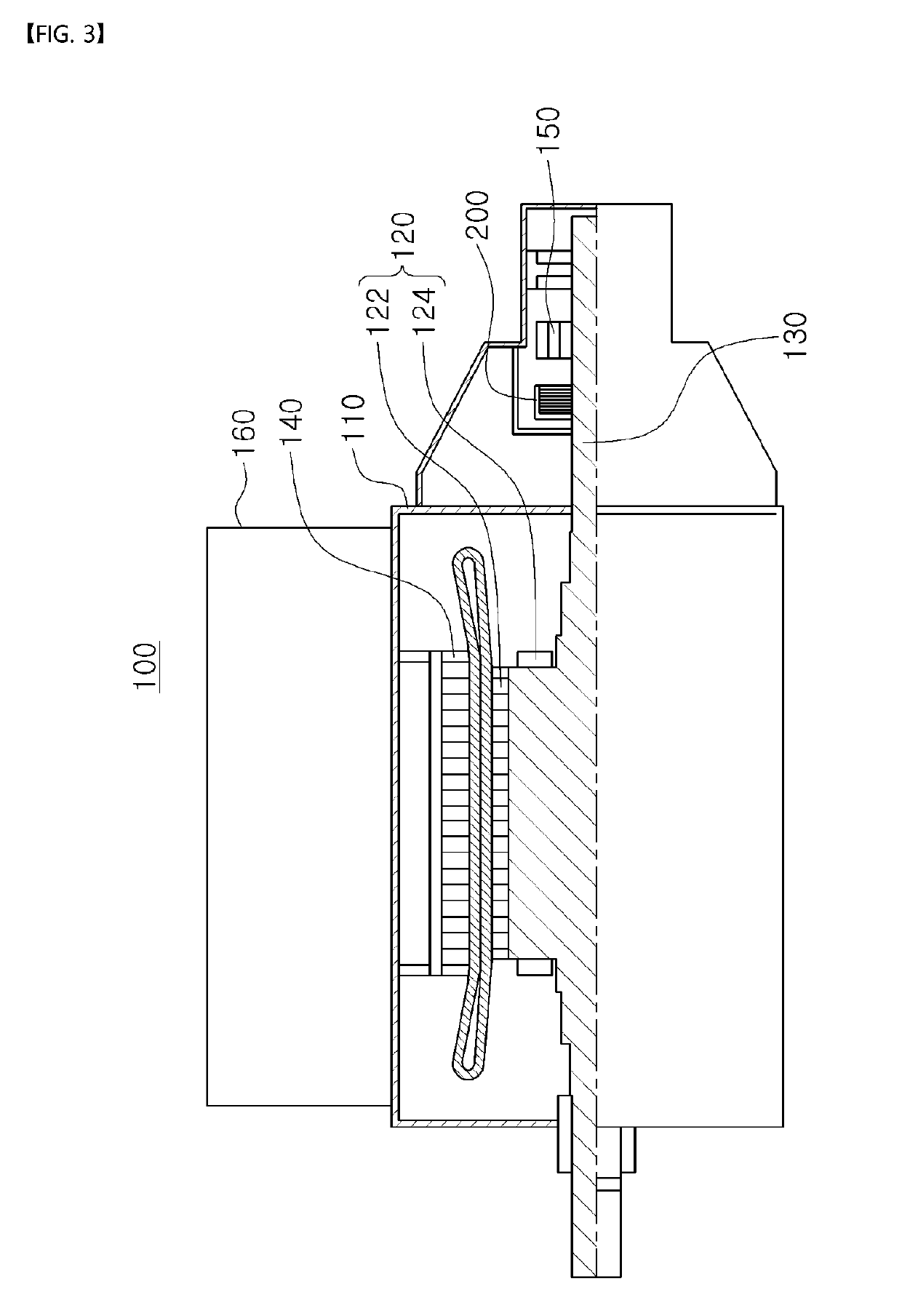
[0030]In the description below, a field discharge resistor unit 200 according to an exemplary embodiment will be described with reference to FIGS. 3 and 4.

[0031]As illustrated in FIGS. 3 and 4, a synchronous motor 100 may include a housing 110, a rotor 120, a rotary shaft 130, a stator 140, an exciter 150, a heat exchanging portion 160, and a field discharge resistor unit 200.

[0032]The housing 110 may form an exterior of the synchronous motor 100 in the exemplary embodiment, and may provide an internal space in which the rotor 120, the rotary shaft 130, and the stator 140 are disposed.

[0033]The rotor 120 may be rotatably provided in the housing 110, and m...


PUM


Abstract

A field discharge resistor unit according to an embodiment of the present invention is a device coupled to a rotary shaft of a synchronous motor and connected to a coil wound on a rotor of the synchronous motor, to reduce a magnitude of an electric current flowing through the coil wound on the rotor, and comprises: a hub which has a receiving space therein and is coupled to the rotary shaft of the synchronous motor so that a rotary movement of the hub matches that of the shaft; and at least one conductor disk received in the receiving space of the hub and may function as a resistor when an electric current flows therethrough.

Description

TECHNICAL FIELD[0001]The present disclosure relates to a field discharge resistor unit and a synchronous motor including the same, and more particularly, to a field discharge resistor unit having improved thermal stability and capable of easily adjusting a resistance value and heat capacity, and a synchronous motor including the same.BACKGROUND ART[0002]A synchronous motor may be a motor configured such that a distributed wound coil is disposed in a stator (an armature), a rotating field may be formed when alternating current power is applied, and the motor may rotate at a velocity the same as a velocity of the rotating field by a magnetic pole applied to the rotating field.[0003]According to a lateral cross-sectional diagram of a synchronous motor illustrated in FIG. 1 of the related art, a synchronous motor may include a field discharge resistor (FDR) 10 coupled to a rotary shaft. The field discharge resistor may reduce a magnitude of current flowing in a coil 20 wound on a rotor ...

Claims


Application Information

Patent Timeline
IPC IPC(8): H02K11/26H02K9/06H02K19/14
CPCH02K11/26H02K9/06H02K19/14H02K11/0094H02K19/02
Inventor JUNG, SEUNG-WOOKJEON, MOO-JONGOH, JE-GEUNJANG, CHUNG-MAN
Owner HYUNDAI ELECTRIC & ENERGY SYST CO LTD
Why Eureka
Try Eureka