
LED light bulb and LED light-emitting strip being capable of emitting 4TT light

a technology of led light emitting strips and led light bulbs, which is applied in the direction of point-like light sources, semiconductor devices of light sources, lighting and heating apparatus, etc., can solve the problems of high cost, low efficiency, and difficulty in popularization, and achieve the effect of reducing the glare of led chips, improving the internal quantum efficiency of led chips, and increasing the price of chips

Active Publication Date: 2016-02-16
ZHEJIANG LEDISON OPTOELECTRONICS
View PDF50 Cites 39 Cited by
  • Summary
  • Abstract
  • Description
  • Claims
  • Application Information

AI Technical Summary

Benefits of technology

[0015]Accordingly, one object of the present invention is to provide a LED light emitting strip being capable of emitting 4π light with a high efficiency.
[0063]As the internal quantum efficiency of LED chips is further improved, and the price of the chips is continually decreased, the LED light bulb with LED chips emitting 4π light of the present invention may become a primary form of the LED general lighting lamp.

Problems solved by technology

The main problems for the current LED light bulb lie in too high costs and sale prices, which are several times those of the energy-saving fluorescent lamps at the condition of same luminous flux, thereby being difficult to popularize.
The factor resulting in high cost is not caused by the LED chip itself, but by the high cost aluminum alloy heat sink, the driver comprising a switching mode power supply having a transformer and a constant-current device as well as LED packaging.
Such driver not only has a high cost, but also has a low efficiency.
That is, LED light bulb in the prior art for replacing the incandescent lamp has a relatively low luminescent efficiency of the entire light, too high cost, and not much long lifetime.
However, this does not solve a problem of heat dissipation of the chip.
This chip is suspended without a support plate and thus the power leads on the chip have a poor reliability.
Thus, only a single small power chip can be used, and it is difficult to produce a reliable light having sufficient output light flux.
As described in the above US patent application, this the transparent thermal conducting substrate such as sapphire and diamond is very expensive and is difficult to be practical; and since the copper, SiC and the like are not transparent, it is impossible to achieve emitting 4π light.
The path of dissipating heat ends the bulb head, resulting in a difficulty of making a thermal connection and a limited effect of dissipating heat.
If the bulb head has the driver for the LED, then it will cause the path of dissipating heat to be disrupted and failed.
Therefore, it is difficult to produce a practical light having sufficient output luminous flux.
How to dissipate so much heat is always a critical problem since this type of power LED first appears.
To the present day, the heat dissipation is still one critical problem of this type of low voltage and high current power type LED lighting, including LED light bulbs.
This metal heat sink is typically made of aluminum alloy and has a bulky volume, a heavy weight and a high price.
It is one of critical factors for high cost of the LED light bulb in the prior art.
On the other hand, since the coefficient of viscosity of the liquid is very large, for example, water having 8937 μP of viscosity, it is difficult for them to create convection.
Concerning the above, the liquid has poor effects of thermal conduction and convection heat dissipation.
Moreover, the use of liquid to dissipate heat also gives rise to the problems such as electroanalysis of the liquid, erosion of the liquid to the LED, the heat dissipation failure or even explosion caused by formation of a gas phase layer at a surface of LED likely due to the phase transition of the liquid, the liquid contamination caused after the breakage of the bulb shell, and the heavy weight.
Thus, it is not easy to practically use and popularize it.
These methods are not practically used up to now.
But it is difficult to create a limited convection, resulting in the limited effect of thermal conduction and dissipation, since the tube of the cold cathode fluorescent lamp has a large volume, which nearly occupies all the bulb shell.
However, these lamps are different from the LED light.
Besides the above problem of heat dissipation, the LED light bulb in the prior art also has a driving problem of transforming the commercial high voltage power into the low voltage and high current.
Since the volume of the LED light for replacing the incandescent lamp is not too large, the volume of the driver and the transformers should be kept as small as possible, while the difference between the input voltage and the output voltage is very large; this results in a low efficiency for electrical transformation, typically 70%-80%.
This reduces the luminescent efficiency of the entire light.
Meanwhile, because its efficiency is low, it generates a large amount of heat.
Taking into consideration of the above generated heat by the driver and the heat generated by LED, the temperature of the driver will readily rise, thus this does not only further decrease the efficiency of the driver, but also will shorten lifetime of the driver.
As temperature rises, their efficiency, lifetime and reliability will be significantly reduced.
Moreover, the driver containing the switching power supply with the transformer and the constant current circuit has a complicated circuit and a high requirement on the elements, thus the cost thereof is high, which is another critical factor of leading to the high price of the prior art LED light bulb.
However, such LED currently has a relatively low efficiency, and it needs to tightly and thermally connect to a metal heat sink which has to be exposed in the air.
Since ACLED is connected with a high voltage of alternating current, the metal heat sink will easily be charged and thus be unsafe.
The prior art HVLED (high voltage LED), for example as described in Chinese Patent No. 201020159200.9, also has the same safety issues.
If a person looks it in the eye directly, and will create a strong glare, thus leaving a shadow in the field of vision, then the eyesight will be heavily impacted within a short time.
In order to obtain a good feel for the light, a light diffusing layer of the antidazzle bulb shell needs to have a sufficient thickness, while this will also reduce the transmission efficiency of the bulb shell.
This in turn reduces the luminescent efficiency of the entire light.

Method used


Image

  • LED light bulb and LED light-emitting strip being capable of emitting 4TT light
  • LED light bulb and LED light-emitting strip being capable of emitting 4TT light
  • LED light bulb and LED light-emitting strip being capable of emitting 4TT light

Examples


Embodiment Construction

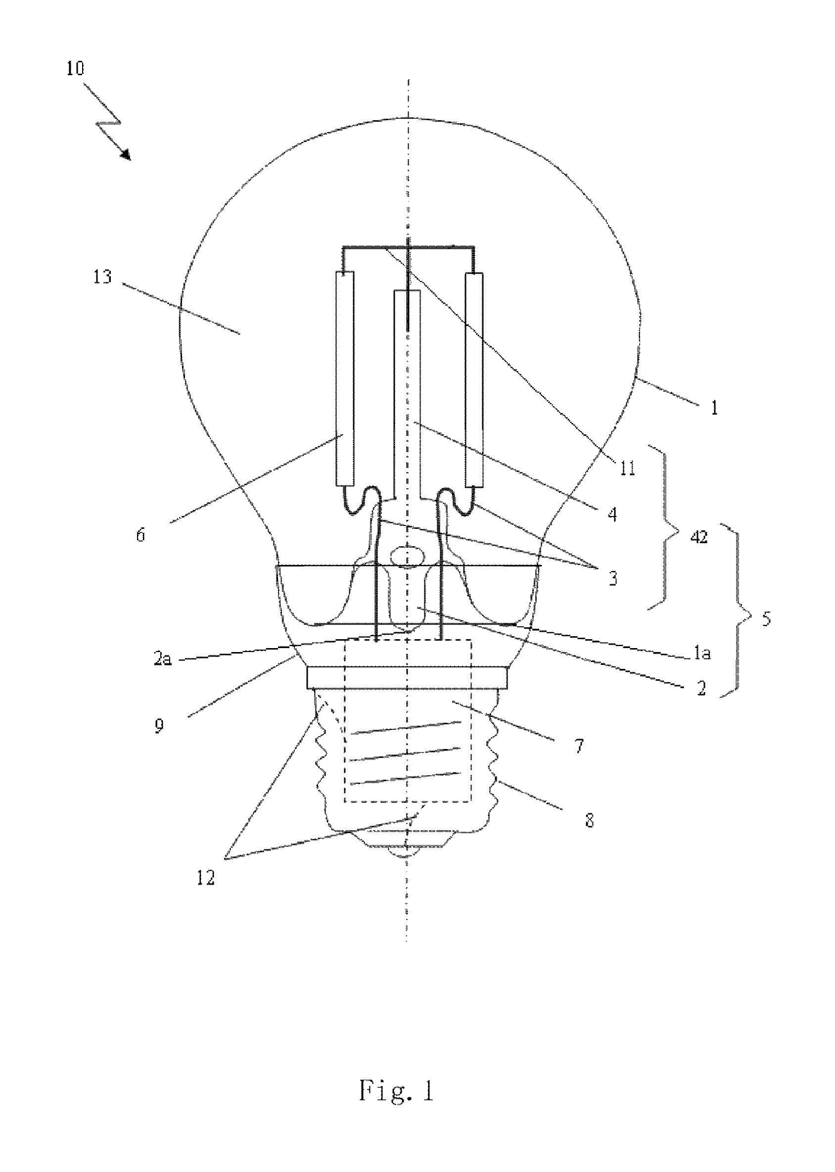
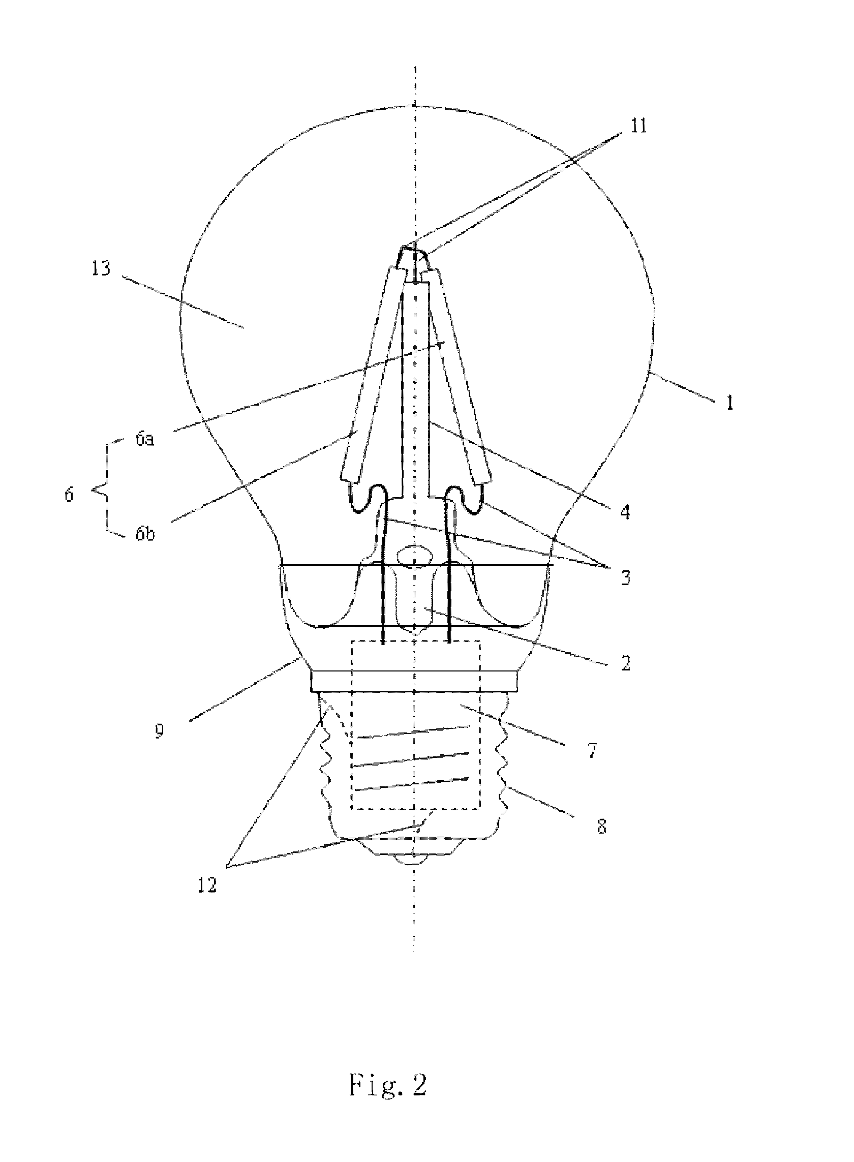
[0134]The technical solution of the present invention will be further explained in detail, by the following embodiments, with reference to FIGS. 1-21. Throughout the specification, the same or similar reference numerals will indicate the same or similar components. The explanation to the implementing of the present invention with reference to the accompanying drawing is intended to interpret the general inventive concept of the present invention, instead of limiting the present invention.

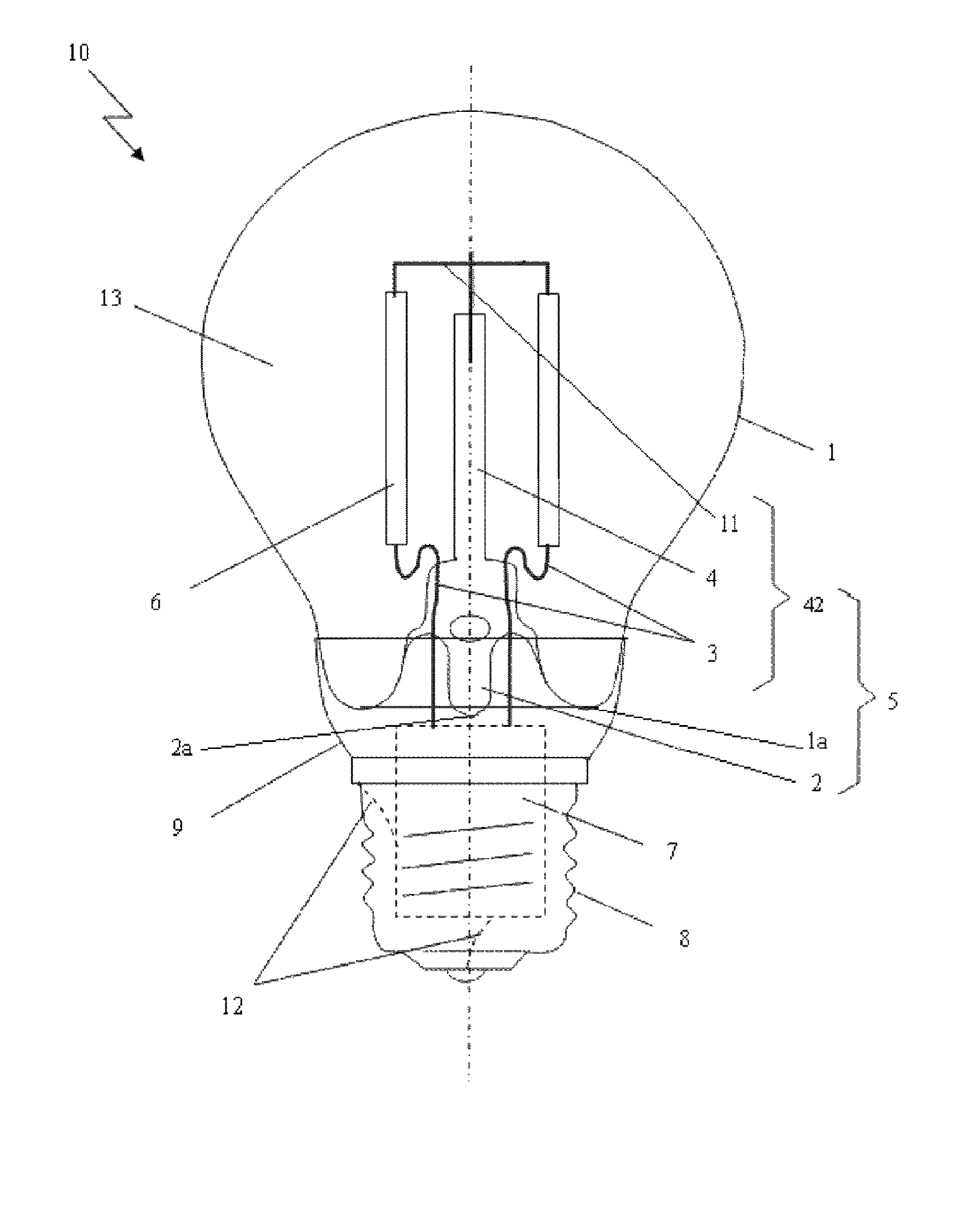
[0135]With referring to FIG. 1, it is a schematic structure view of highly efficient LED light bulb with LED chips emitting 4π light in accordance with one embodiment of the present invention. This LED light bulb includes a light-transmission bulb shell 1 of LED light, a core column 5 with an exhaust tube 2 and a bracket, at least one LED light emitting strip 6 having a LED chip emitting 4π light, a driver 7, an electrical connector 8, a connecting piece 9 connecting the bulb shell 1 to the electric...


PUM


Abstract

The present invention discloses a LED light bulb, comprising: a LED light bulb shell; a core column with an exhaust tube and a bracket; at least one LED light emitting strip with LED chips therein emitting 4π light; a driver; and an electrical connector, wherein the LED light bulb shell is vacuum sealed with the core column so as to form a vacuum sealed chamber, which is filled with a gas having a low coefficient of viscosity and a high coefficient of thermal conductivity, the bracket and the LED light emitting strips fixed on the bracket are housed in the vacuum sealed chamber, the LED light emitting strip is in turn electrically connected to the driver, the electrical connector, while the electrical connector is used to be electrically connected to an external power supply, so as to light the LED light emitting strips. In addition, the present invention also provides the LED light emitting strips with LED chips emitting 4π light, as used in the LED light bulb.

Description

CROSS-REFERENCE TO RELATED APPLICATION[0001]This application is a Continuation-In-Part under 35 U.S.C. §111(a) of PCT / CN2011 / 079234, filed Sep. 1, 2011 (currently pending), which claims the benefit under 35 U.S.C. §119, to: Chinese Patent Application No. 201010278760.0, filed Sep. 8, 2010; Chinese Patent Application No. 201020617406.1, filed Nov. 22, 2010; Chinese Patent Application No. 201010610092.7, filed Dec. 29, 2010; Chinese Patent Application No. 201020685204.0, filed Dec. 29, 2010; Chinese Patent Application No. 201120148195.6, filed May 11, 2011; Chinese Patent Application No. 201120148206.0, filed May 11, 2011; Chinese Patent Application No. 201120319651.9, filed Aug. 29, 2011,” the disclosures of which are incorporated herein by reference.FIELD OF INVENTION[0002]The present invention relates to a field of lighting techniques, more particularly, to a LED light emitting strip and a light bulb using the same.BACKGROUND OF INVENTION[0003]In prior art, a LED light bulb in plac...

Claims


Application Information

Patent Timeline
Patent Type & Authority Patents(United States)
IPC IPC(8): F21V19/00F21K99/00F21V3/00F21V29/00F21Y101/02F21Y111/00F21Y103/00
CPCF21K9/135F21K9/17F21V3/00F21V19/003F21V19/005F21V19/0035F21V29/004F21Y2101/02F21Y2103/003F21Y2111/001F21V29/70F21K9/232F21K9/27F21K9/66F21Y2103/10F21Y2107/00F21Y2115/10H01L2224/48091H05B45/357H01L2924/00014F21V19/00F21V23/00F21V29/00
Inventor GE, SHICHAOLIU, HUABINGE
Owner ZHEJIANG LEDISON OPTOELECTRONICS
Learn More