
Laser frequency adjustment method and laser frequency adjustment system

a laser frequency adjustment and laser technology, applied in the field of flat panel display technology, can solve the problems of inability to conduct a more thorough study of the crystallization process of polysilicon, and inability to further improve the process, so as to achieve effective widening of the frequency range of lasers, low power consumption, and high speed

Active Publication Date: 2016-01-12
TCL CHINA STAR OPTOELECTRONICS TECH CO LTD
View PDF3 Cites 0 Cited by
  • Summary
  • Abstract
  • Description
  • Claims
  • Application Information

AI Technical Summary

Benefits of technology

This approach effectively widens the laser frequency range, allowing for more efficient irradiation of the substrate, thereby improving the poly-silicon crystallization results and enabling real-time adjustments for better process control.

Problems solved by technology

Although adjusting parameters of the laser beam may better the result of crystallization, due to limitation imposed by the specifications of operation machines, parameters and the ranges thereof that can be modulated are limited, such as laser frequency, so that it is impossible to conduct more thorough study of the process of crystallization of poly-silicon and the result thereof.
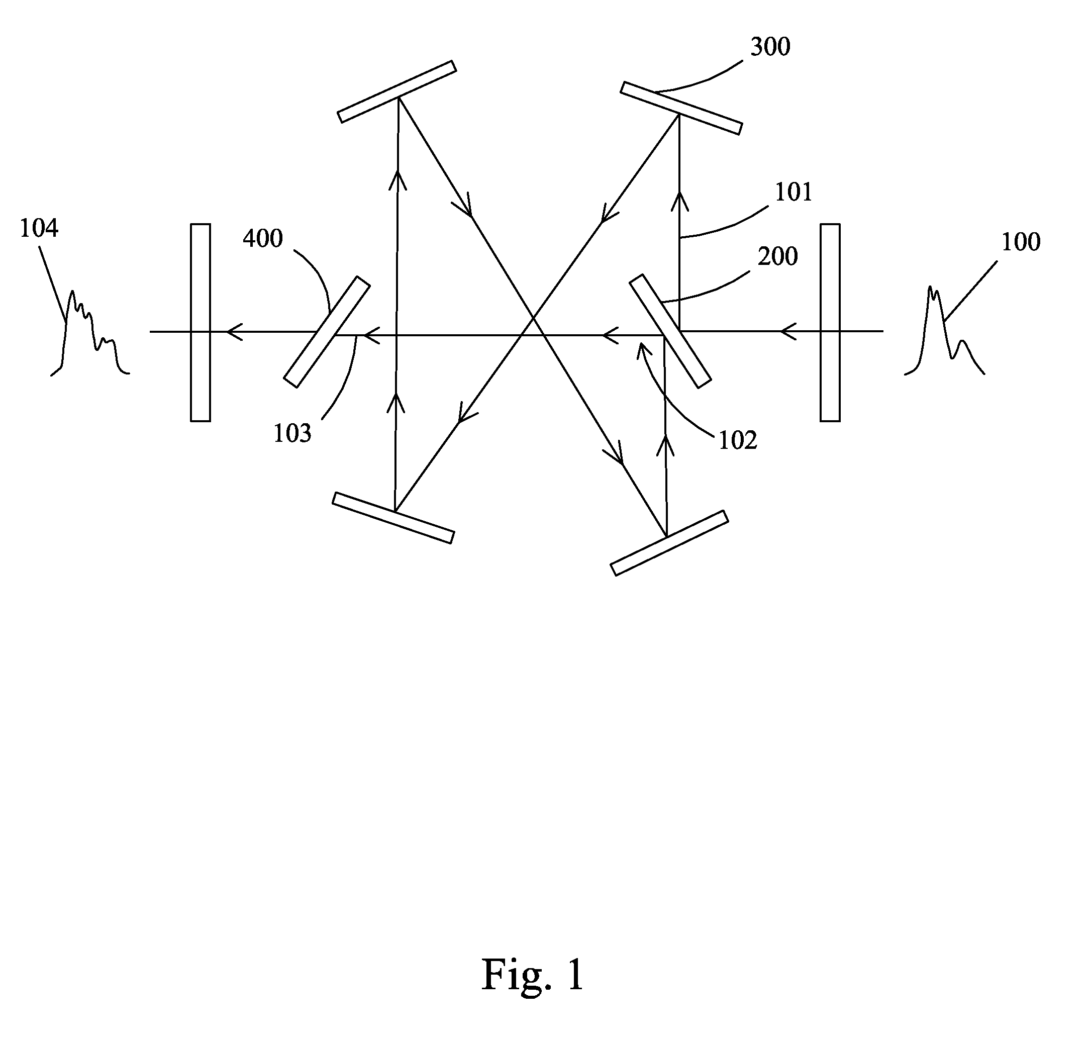
Due to constraints imposed by the specifications of the operation machines, the four reflectors 300 shown in FIG. 1 are all fixed in position, which is not adjustable, so that the laser pulse 104 that is finally formed is fixed, making it not possible to further improve the process and result of crystallization of poly-silicon.

Method used


Image

  • Laser frequency adjustment method and laser frequency adjustment system
  • Laser frequency adjustment method and laser frequency adjustment system
  • Laser frequency adjustment method and laser frequency adjustment system

Examples


Embodiment Construction

[0044]To further expound the technical solution adopted in the present invention and the advantages thereof, a detailed description is given to a preferred embodiment of the present invention and the attached drawings.

[0045]The present invention makes improvement in respect of frequency parameters of a laser pulse as a link of a laser annealing process in order to expand the range of frequency adjustability thereby enhancing the crystallization result of poly-silicon. The present invention is realized through such a way that with a laser pulse passing through a beam splitter and split into two sub-laser pulses, an optical length extension (OLEX) device is arranged on an optical path of one of the sub-laser pulses to further expand the optical path difference of the two sub-laser pulses so that the two sub-laser pulses can be more clearly distinguished from each other after passing through the beam splitter, whereby frequency adjustment of the laser pulse can be realized through supe...


PUM


Abstract

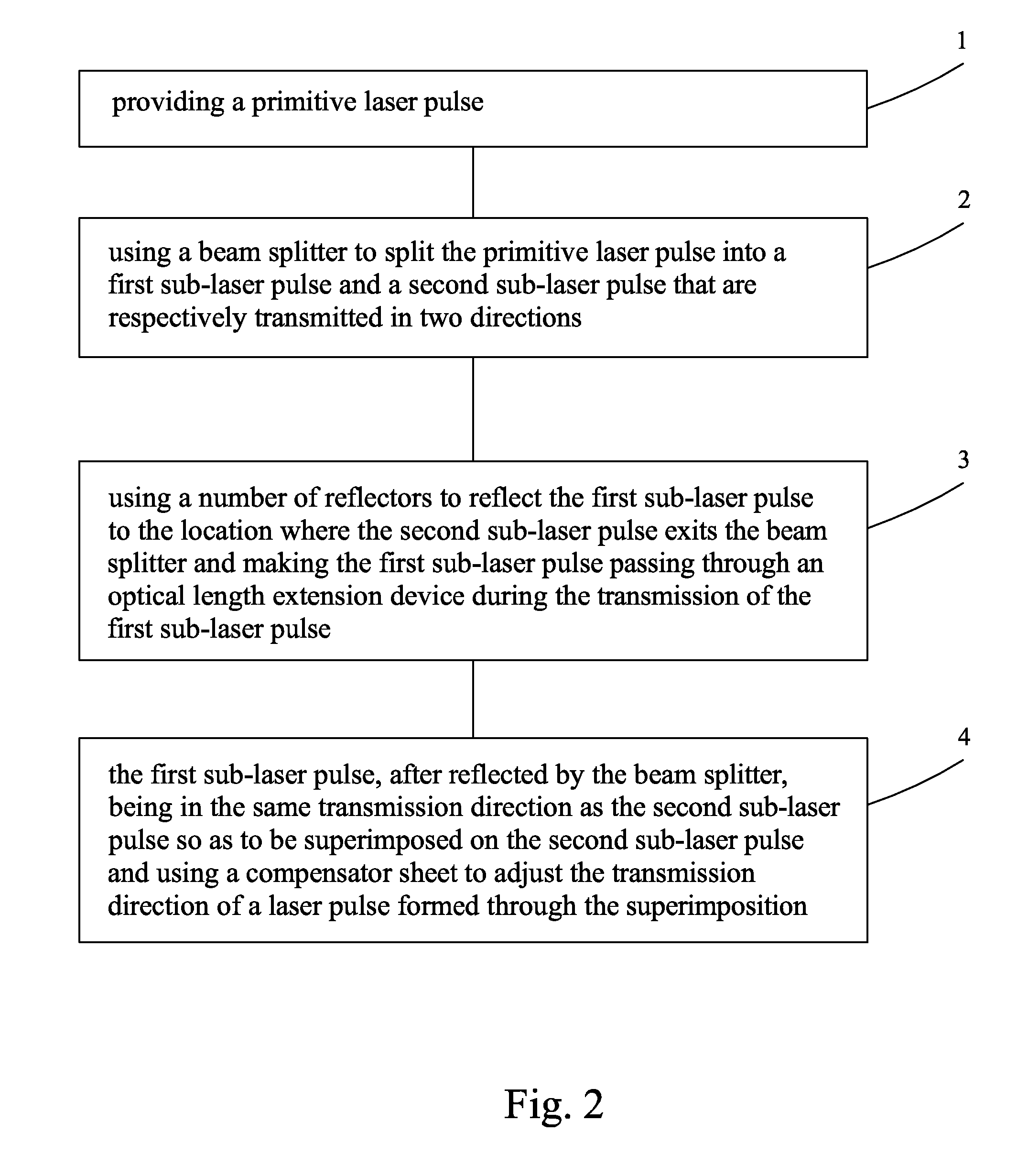
The present invention provides a laser frequency adjustment method and a laser frequency adjustment system. The laser frequency adjustment method includes: (1) providing a primitive laser pulse (10); (2) using a beam splitter (20) to split the primitive laser pulse (10) into a first sub-laser pulse (11) and a second sub-laser pulse (12); (3) using a plurality of reflectors (30) to reflect the first sub-laser pulse (11) to a location where the second sub-laser pulse (12) exits the beam splitter (20) and making the first sub-laser pulse (11) passing through an optical length extension device (40) during the transmission of the first sub-laser pulse (11); and (4) superimposing the first sub-laser pulse (11) and the second sub-laser pulse (12) and using a compensator sheet (50) to adjust the transmission direction of the superimposed laser pulse (13).

Description

BACKGROUND OF THE INVENTION[0001]1. Field of the Invention[0002]The present invention relates to flat panel displaying technology, and in particular to a laser frequency adjustment method and a laser frequency adjustment system.[0003]2. The Related Arts[0004]The displaying technology has been undergone fast development recently. A flat panel display device is significantly different from a traditional video image displaying device by adopting totally different displaying and manufacturing technology. The traditional video image displaying device is generally based on a cathode ray tube (CRT), from which a flat panel display device differs primarily concerning changes made in respect of weight and size (thickness). Generally, a flat panel display device has a thickness not greater than 10 centimeters, among the other differences associated with various technical aspects, such as theory of displaying, manufacturing material, manufacturing process, driving for displaying video images.[...

Claims


Application Information

Patent Timeline
Patent Type & Authority Patents(United States)
IPC IPC(8): G02B27/14G02B27/09
CPCG02B27/0927
Inventor ZHANG, XIANG
Owner TCL CHINA STAR OPTOELECTRONICS TECH CO LTD
Learn More