
CO2 composite spray method and apparatus

a composite spray and carbon dioxide technology, applied in the field of carbon dioxide (co2) solidgas composite sprays, can solve the problems of high cost, inability to clean impure carbon dioxide, and inability to obtain pristine surfaces clean,

Active Publication Date: 2015-12-29
HITACHI HIGH-TECH CORP
View PDF10 Cites 5 Cited by
  • Summary
  • Abstract
  • Description
  • Claims
  • Application Information

AI Technical Summary

Benefits of technology

The patent is about a method and device for producing and delivering small amounts of highly pure carbon dioxide particles. The process involves compressing the liquid carbon dioxide to a high pressure, which is then converted into a cloud of small particles using a special condenser. The resulting particles have uniform density and distribution. The patent also describes a spray nozzle that can adjust the size of the carbon dioxide particles for different uses. The invention is useful for creating a carbon dioxide composite spray system.

Problems solved by technology

In fact, the solid / gas carbon dioxide spray stream will remove contaminants that the gaseous spray stream is unable to remove at any nozzle exit velocity.
Also, the carbon dioxide available at the time was not very pure or, if it was, it was very expensive.
The impure carbon dioxide could not get pristine surfaces clean without leaving behind an undesirable residue, and the pure but expensive carbon dioxide was cost prohibitive, necessitating the development of dense fluid purification and delivery systems.
These researchers knew from prior experience that critical optical surfaces, such as vapor deposited gold coatings and pristine polished silicon, will adversely change when any physical contact occurs.
The researchers at Hughes were able to improve upon the solid / gas carbon dioxide spray cleaning technology by designing equipment that was much better than the early designs; however, the Hughes Aircraft equipment was extremely expensive.
The main disadvantage of de Laval cryogenic spray nozzles is that there is an unbalancing effect at the nozzle exit of the fluid stream.
This causes the liquid droplets or sublimable solid particles to expand quickly, resulting in a significant loss of cleaning agent (solid particles) through plume expansion or the production of numerous and small solid particles, which generally requires the spray nozzle to be placed in close proximity to a substrate surface to be effective.
However this is counterproductive because the carbon dioxide aerosol particles are shrinking in size, quantity and velocity, all of which adversely affects spray cleaning control and efficiency.
Another shortcoming common to conventional cryogenic spray techniques utilizing de Laval spray nozzle designs is the intrusion and entrainment of atmospheric contaminants into the cryogenic particle flow stream.
Wet atmosphere entrained within the cold spray plume boundary is delivered to the surface along with the cleaning spray particles which complicates the cleaning process.
Wetness is caused by the lack of effective shielding of the sublimating particle stream from the ambient atmosphere and insufficient heat capacity within the spray boundary to prevent condensation.
However, much of the CO2 used within a conventional CO2 cleaning spray is excessive and lean sprays produced by same tend to be spongy (gas-filled).
However, up to this point achieving this goal has been illusive with numerous and varied constraints.
Heretofore it has not been possible to achieve high cleaning (or cooling) effectiveness while efficiently generating ultra-small quantities of uniformly distributed CO2 particles within a CO2 Composite Spray as well as more conventional de Laval spray schemes.
The principal drawback of this approach is a significant amount of CO2 is used, between 15 and 50 pounds of CO2 per hour per nozzle or more, to increase spray cleaning effectiveness.
Another significant drawback is that the rapid condensation through a nozzle expansion means produces a very cold and dense spray that lacks particle size and spray density uniformity.
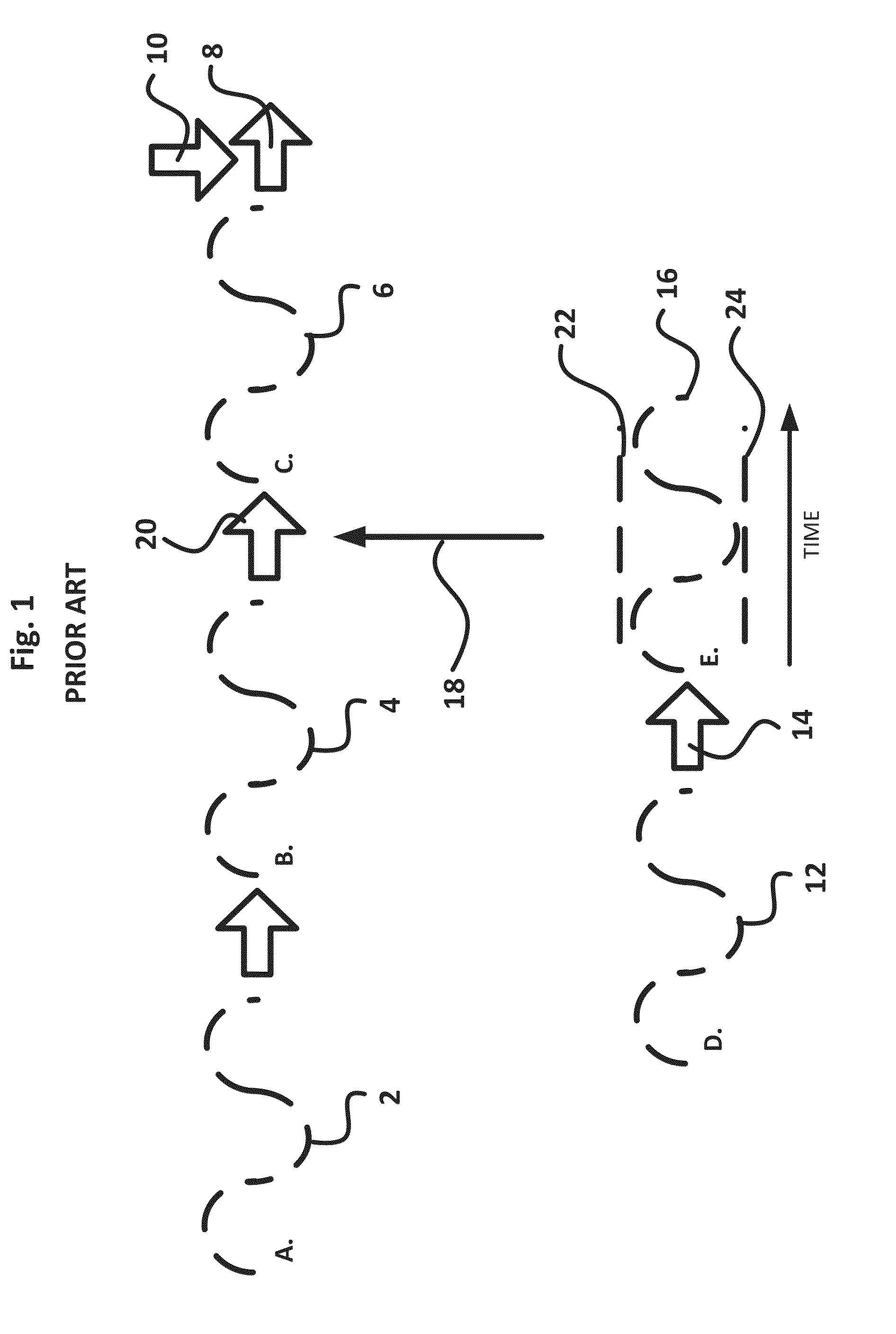
An 18-turn metering valve used to control saturated liquid CO2 capillary injection in the range between 0.1 to 2 turns, representing a flow orifice adjustment range of between approximately 0.001 and 0.004 inches, results in clogging, sputtering, choking and sinusoidal-like spray fluctuations due to the saturated liquid CO2 boiling (cooling, pressure dropping and expansion) within the metering valve body and internal capillary segments.
This problem is greatly worsened using shorter segments of these capillaries, for example using a 0.030 ID capillary with a capillary condenser loop segment shorter than 36 inches in length.
All of these constraints result in downstream particle injection fluctuations from the capillary condenser and within the coaxial propellant gas mixing nozzle—resulting in cleaning or cooling spray composition fluctuations in the lower saturated liquid CO2 injection ranges of between 0.1 and 3 pounds per hour per nozzle.
Although the fluctuations do diminish as the liquid CO2 injection rate is increased, which is wasteful, it is common to have spray instability below capillary injection rates of 3 to 5 pounds CO2 per hour using a 0.030 inch ID capillary condenser, for example.
CO2 Composite Spray fluctuations are problematic for applications requiring precise process control—for example fixed precision cleaning rates or cooling rates.
The problem with reactive control is that the spray mixing temperature must be measured at a distance downstream from the nozzle exit to assure a fully mixed composite spray.
Moreover this procedure is not real-time and is basically always drifting out of control above or below the UCL and LCL set points.
Finally, the PC or PLC, software and automated temperature measurement and mechanical valve controls needed for this reactive control scheme add significant cost and complexity to a CO2 Composite Spray system.
The cleaning sprays produced by the prior art habitually drift during use, and variably produce either too lean or too rich CO2 cleaning sprays.

Method used


Image

  • CO<sub>2 </sub>composite spray method and apparatus
  • CO<sub>2 </sub>composite spray method and apparatus
  • CO<sub>2 </sub>composite spray method and apparatus

Examples


experimental 1

[0101]Having thus described the preferred and exemplary embodiments of the present invention, the following discussion by reference to FIGS. 9A, 9B, 9C, 9D, 9E and 9F details experimental testing, results, and analysis comparing and contrasting the performance characteristics between the present invention with the prior art—specifically prior-art and first-generation spray cleaning system described and operated under U.S. Pat. No. 5,725,154 (U.S. Pat. No. '154) and prior-art and second-generation spray cleaning system described and operated under U.S. Pat. No. 7,451,941 (U.S. Pat. No. '941) spray system scheme modified with a stepped capillary system described under U.S. Pat. No. 7,293,570 (U.S. Pat. No. '570). All CO2 composite spray cleaning systems tested under operated under equivalent dense fluid propellant gas pressure and temperature conditions.

Test Apparatus and Conditions for the Present Invention:

[0102]A commercial CO2 composite spray system called the PowerSno™ CO2 compos...

experimental 2

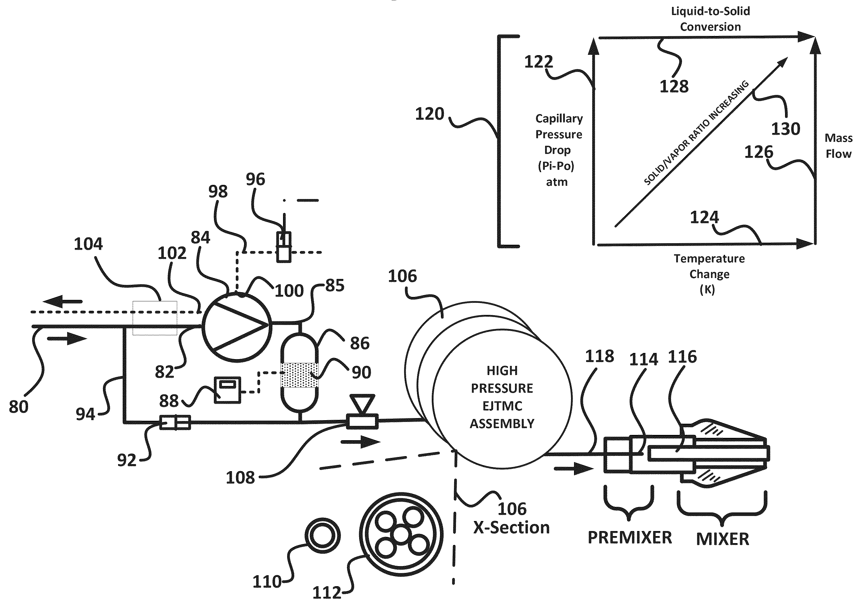
[0118]An experiment was performed to determine the relationship between spray mixing temperature of a CO2 Composite Spray with the variation in micro-capillary pressure of within the EJTMC assembly.

Spray Power Test Apparatus and Method:

[0119]The present invention was tested to determine the changes in composite spray mixing temperature for an exemplary high pressure micro-capillary while maintaining a fixed mixing propellant gas (clean dry air) pressure, flow rate and temperature. The test apparatus for the present experiment comprised a prior-art PowerSno™ Model PS6000 CO2 spray system modified with the apparatus of FIG. 4A and FIG. 4B. The mixing spray nozzle of FIG. 4B was positioned 0.25 inches from a K-Type thermocouple connected to a digital thermometerOmega Model CL23A, Omega Engineering. The EJTMC high-pressure condenser of FIG. 4A (106) comprised a 12 inch long micro-capillary having an internal diameter of 0.008 inches positioned coaxially (and adjustably) within the spr...


PUM

PropertyMeasurementUnit
densityaaaaaaaaaa
inner diameteraaaaaaaaaa

Abstract

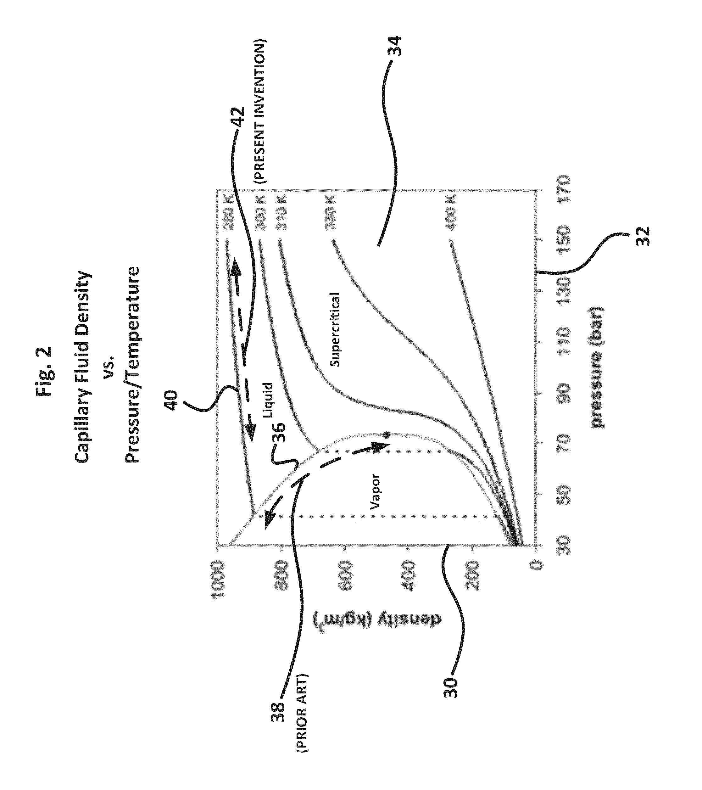
A method and apparatus is disclosed for the production, delivery and control of microscopic quantities of minute solid carbon dioxide (CO2) particles having uniform density and distribution for use in a CO2 Composite Spray process, which employs compression of liquid carbon dioxide to form a supersaturated liquid, which is then condensed via micro-capillaries into minute and highly energetic solid carbon dioxide particles, which are injected into a propellant gas stream.

Description

PRIORITY CLAIM[0001]This application claims the benefit of U.S. Provisional Patent Application 61 / 836,635 (filed 18 Jun. 2013) and 61 / 836,636 (filed 18 Jun. 2013), which are all incorporated by reference.BACKGROUNDField of Invention[0002]The present invention relates to a method and apparatus for producing, controlling and projecting a dense fluid spray, and specifically to carbon dioxide (CO2) solid-gas composite sprays such as the CO2 Composite Spray™, a Trademark of CleanLogix LLC, used for precision cleaning, cooling and machining applications. More particularly, the present invention is an improved CO2 Composite Spray cleaning method and apparatus.[0003]Cleaning delicate surfaces with a strong spray stream consisting of sub-micron sized solid carbon dioxide particles propelled by gaseous carbon dioxide was first proposed by S. A. Hoenig (see “The application of dry ice to the removal of particulates from optical apparatus, spacecraft, semiconductor wafers and equipment used in ...

Claims


Application Information

Patent Timeline
Patent Type & Authority Patents(United States)
IPC IPC(8): B05B7/12B08B7/00B24C1/00B24C7/00B65D83/42B65D83/14B05B12/08B05B7/14
CPCB05B12/082B05B7/1486B08B7/00B65D83/752B24C7/0046B65D83/42B24C1/003
Inventor JACKSON, DAVIDMARIAN, LIVIUSOTO, FELIPELEE, JOHN
Owner HITACHI HIGH-TECH CORP
Learn More