
Method of particle contaminant removal

a technology of particle contaminant and removal method, which is applied in the preparation of detergent mixture composition, cleaning using liquids, detergent compositions, etc., can solve the problems of material present in a manufacturing operation as a potential source of contamination, the size of particulate contamination, and the device within the vicinity of the contamination will likely be inoperable, so as to reduce the amount of contamination left, the effect of easy peeling and high velocity

Active Publication Date: 2015-10-13
LAM RES CORP
View PDF37 Cites 3 Cited by
  • Summary
  • Abstract
  • Description
  • Claims
  • Application Information

AI Technical Summary

Benefits of technology

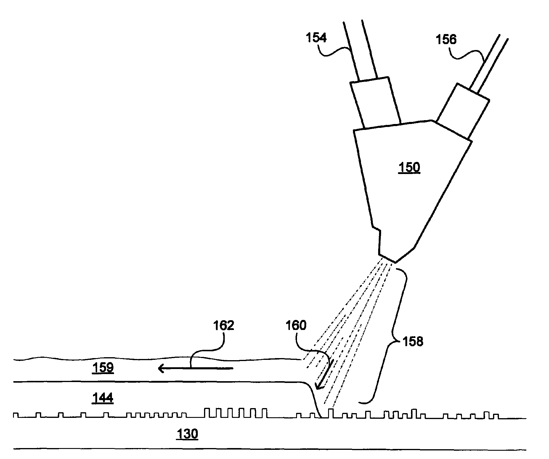
The invention provides a mechanism for removing particles from a solid surface using a viscoelastic material. The viscoelastic material is applied to the surface and then sprayed with a high-velocity liquid to dislodge the material. The centrifugal force of spinning the substrate helps remove the viscoelastic material and any particles attached to it. The resulting surface is clean while keeping the features on the substrate. The invention takes advantage of the solid-like behavior of the viscoelastic material when applied and the liquid-like behavior when removed, making the cleaning process efficient and easy. The invention prevents incomplete or inefficient removal of liquid chemicals and spotting, leading to a more effective cleaning process.

Problems solved by technology

Essentially any material present in a manufacturing operation is a potential source of contamination.
If the particulate contamination is not removed, the devices within the vicinity of the contamination will likely be inoperable.
However, the size of particulate contamination is often on the order of the critical dimension size of features fabricated on the wafer.
Removal of such small particulate contamination without adversely affecting the features on the wafer can be quite difficult.
As feature sizes continue to decrease and become more fragile, the probability of feature damage due to application of mechanical forces on the wafer surface increases.
For example, features having high aspect ratios are vulnerable to toppling or breaking when impacted by a sufficient mechanical force.
To further complicate the cleaning problem, the move toward reduced feature sizes also causes a reduction in the size of particulate contamination.
Particulate contamination of sufficiently small size can find its way into difficult to reach areas on the wafer surface, such as in a trench surrounded by high aspect ratio features.
Thus, efficient and non-damaging removal of contaminants during modern semiconductor fabrication represents a continuing challenge to be met by continuing advances in wafer cleaning technology.

Method used


Image

  • Method of particle contaminant removal
  • Method of particle contaminant removal
  • Method of particle contaminant removal

Examples


Embodiment Construction

[0029]Several embodiments for effectively removing particle contaminants from a solid surface are now described. It will be obvious, however, to one skilled in the art, that the present invention may be practiced without some or all of these specific details. In other instances, well known process operations have not been described in detail in order not to unnecessarily obscure the present invention.

[0030]Embodiments of the invention provide a particle removal mechanism for cleaning a solid surface using a viscoelastic material and providing a spray jet to apply a liquid at high velocity to the viscoelastic material. The viscoelastic material is selected such that the chemical structure of the material allows for at least partial binding or interaction with particle contaminants that are to be removed from the solid surface. The viscoelastic material is applied to the solid surface as a liquid; however, the time duration of the force applied by the high velocity liquid is shorter t...


PUM

PropertyMeasurementUnit
velocityaaaaaaaaaa
velocityaaaaaaaaaa
velocityaaaaaaaaaa

Abstract

Apparatus and methods for removing particle contaminants from a solid surface includes providing a layer of a viscoelastic material on the solid surface. The viscoelastic material is applied as a thin film and exhibits substantial liquid-like characteristics. The viscoelastic material at least partially binds with the particle contaminants. A high velocity liquid is applied to the viscoelastic material, such that the viscoelastic material exhibits solid-like behavior. The viscoelastic material is thus dislodged from the solid surface along with the particle contaminants, thereby cleaning the solid surface of the particle contaminants.

Description

CROSS REFERENCE TO RELATED APPLICATION[0001]This application is related to U.S. patent application Ser. No. 12 / 131,654 filed on Jun. 2, 2008, and entitled “MATERIALS FOR PARTICLE REMOVAL BY SINGLE-PHASE AND TWO-PHASE MEDIA,” and to U.S. patent application Ser. No. 12 / 165,577, filed on Jun. 30, 2008, entitled “SINGLE SUBSTRATE PROCESSING HEAD FOR PARTICLE REMOVAL USING LOW VISCOSITY FLUID.” This application is also related to U.S. patent application Ser. No. 12 / 262,094 filed on Oct. 30, 2008, and entitled “ACOUSTIC ASSISTED SINGLE WAFER WET CLEAN FOR SEMICONDUCTOR WAFER PROCESS,” and to U.S. patent application Ser. No. 12 / 401,590 filed on Mar. 10, 2009, entitled “METHOD OF PARTICLE CONTAMINANT REMOVAL,” and to U.S. patent application Ser. No. 12 / 423,759 filed on Apr. 14, 2009, entitled “APPARATUS AND METHOD FOR USING A VISCOELASTIC CLEANING MATERIAL TO REMOVE PARTICLES ON A SUBSTRATE.” The aforementioned patent applications are incorporated herein by reference.BACKGROUND[0002]In the ...

Claims


Application Information

Patent Timeline
Patent Type & Authority Patents(United States)
IPC IPC(8): B08B3/10B08B7/00H01L21/67H01L21/02C11D11/00C11D17/04
CPCH01L21/67051B08B3/10B08B7/0014H01L21/02057H01L21/02052C11D17/049C11D11/0047C11D11/0058C11D2111/42C11D2111/22H01L21/302
Inventor KAWAGUCHI, MARK NAOSHIMUI, DAVIDWILCOXSON, MARK
Owner LAM RES CORP
Learn More