Simulation execution method, program, and system

a technology for automobile control and execution method, applied in the direction of cad circuit design, instrumentation, design optimisation/simulation, etc., can solve the problems of large amount of control software, large amount of manpower, and long time-consuming product, and achieve the effect of sacrificing the accuracy of data update timing and increasing the speed of parallel running of logical processes

Inactive Publication Date: 2015-09-22
INT BUSINESS MASCH CORP
View PDF5 Cites 0 Cited by
  • Summary
  • Abstract
  • Description
  • Claims
  • Application Information

AI Technical Summary

Benefits of technology

[0028]This invention advantageously provided a technique for increasing the speed of parallel running of logical processes without sacrificing the accuracy of data update timing in a parallel discrete event simulation system.

Problems solved by technology

Although these are mechatronics devices in nature, they also incorporate large amounts of control software.
Therefore, the development of such a product has required to spend a long time period, enormous costs and a large pool of manpower to develop a control program and test the program.
However, in HILS, the dedicated hardware device is used, and the device and the real ECU have to be physically wired.
Thus, HILS involves a lot of preparation.
Further, when a test is conducted by replacing the ECU with another, the device and the ECU have to be physically reconnected, requiring even more work.
Further, since the test uses the real ECU, it takes an actual time to conduct the test.
Therefore, it takes an immense amount of time to test many scenarios.
In addition, the hardware device for emulation of HILS is generally very expensive.
This is because past-time processing cannot be requested.
2(3) can also occur in the sense that data transmission is performed immediately even between ECU emulators and between plant simulators but data reception involves a communication delay.
A similar problem can also arise if the time lag is not zero but very small.
However, when the time lag is zero, no future time is given to the null message, deadlock is not caused but parallel execution cannot be achieved.
In this case, errors are accumulated due to inaccurate data switching timings.
In order to increase accuracy, it is necessary to reduce the value of ε, but when it happens, the execution speed is reduced, resulting in a tradeoff between accuracy and execution speed.

Method used


Image

  • Simulation execution method, program, and system
  • Simulation execution method, program, and system
  • Simulation execution method, program, and system

Examples


Embodiment Construction

[0054]The configuration and processing of one preferred embodiment of the present invention will now be described with reference to the accompanying drawings. In the following description, the same components are denoted by the same reference numerals throughout the drawings unless otherwise noted. Although the following will describe the configuration and processing as one embodiment, it should be understood that the technical scope of the present invention is not intended to be limited to this embodiment.

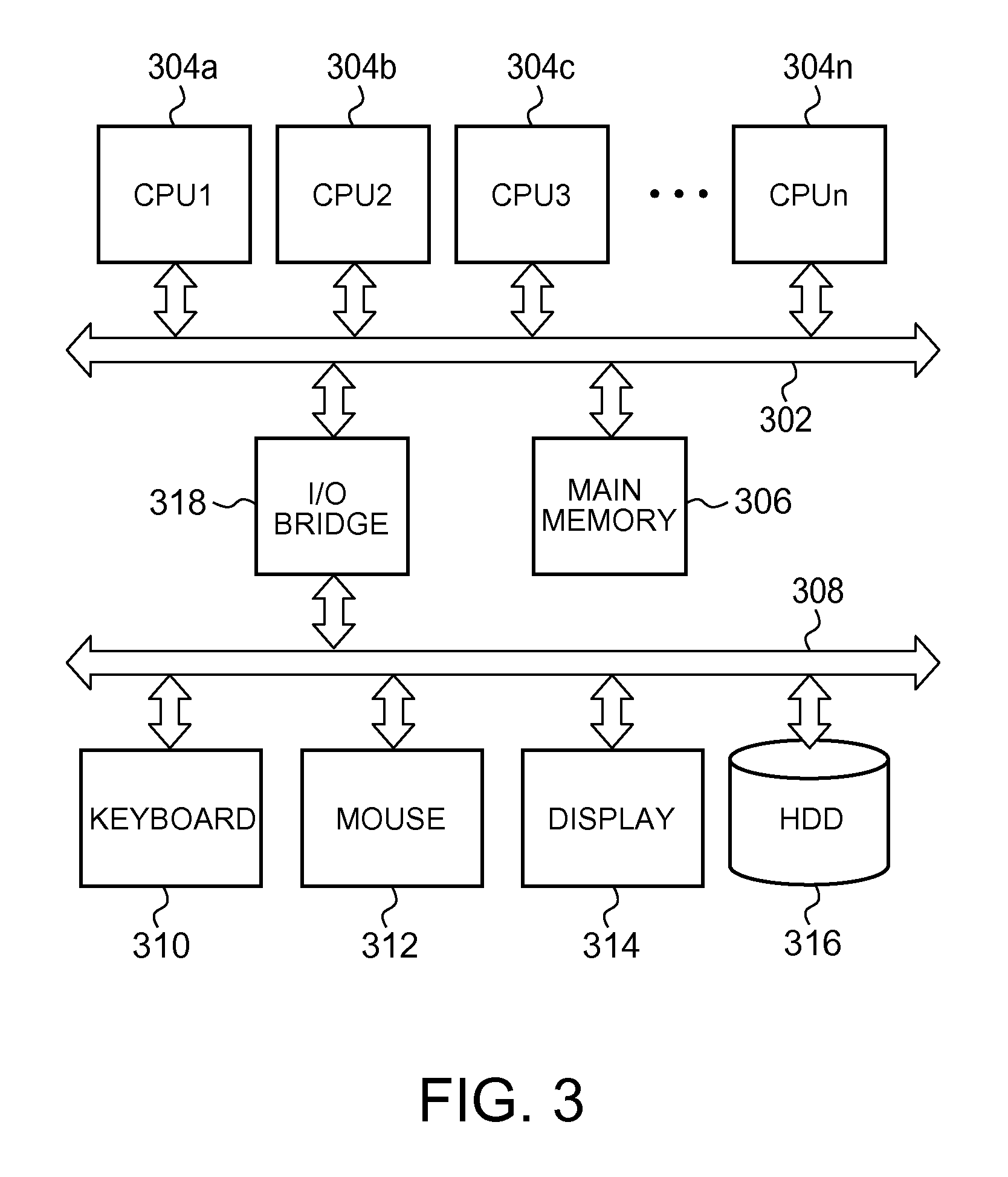
[0055]First, the hardware of a computer used to carry out the present invention will be described with reference to FIG. 3. In FIG. 3, multiple CPUs, i.e., CPU1304a, CPU2304b, CPU3304c, . . . , CPUn 304n are connected to a host bus 302. A main memory 306 is also connected to the host bus 302 for arithmetic processing performed by the CPU1304a, CPU2304b, CPU3304c, . . . , CPUn 304n.

[0056]On the other hand, a keyboard 310, a mouse 312, a display 314, and a hard disk drive 316 are c...


PUM


Abstract

A technique for increasing the speed of parallel running of logical processes without sacrificing the accuracy of data update timing in a parallel discrete event simulation system.A logical process involving a longer receiving time lag than that of sending is executed by an amount of initial shift for a predetermined period before the simulation. The initial shift is set to be one-half of a value of difference between the receiving time lag and the sending time lag. The logical process executed with timing displaced by the amount of initial shift runs by exchanging null messages with each other. Each null message is delivered to a correspondent logical process after the predetermined time lag, and each logical process further sends the correspondent logical process a null message upon receipt of the null message. Thus, there is a progression of simulation by synchronizing them through the null messages.

Description

FIELD OF THE INVENTION[0001]This invention relates to a technique for executing a simulation of an automobile control system or the like.BACKGROUND ART[0002]Recently, a so-called multiprocessor system having multiple processors has been used in the fields of scientific computation, simulation and the like. Meanwhile, in the field of simulation, the development of which has been particularly facilitated only recently, there is simulation software for plants of mechatronics products, such as robots, automobiles, and airplanes. With the benefit of the development of electronic components and software technology, most parts of a robot, an automobile, an airplane, and the like are electronically controlled by using wire connections laid like a network of nerves, a wireless LAN, or the like.[0003]Although these are mechatronics devices in nature, they also incorporate large amounts of control software. Therefore, the development of such a product has required to spend a long time period, ...

Claims


Application Information

Patent Timeline
Patent Type & Authority Patents(United States)
IPC IPC(8): G06F17/50G06F11/26
CPCG06F17/5009G06F11/261G06F17/5022G06F2217/86G06F2117/08G06F30/33G06F30/20G06F30/3308
Inventor MURASE, MASANASHIMIZU, SHUZHANG, GANG
Owner INT BUSINESS MASCH CORP
Why Eureka
Try Eureka