Control unit for a restraint system in a vehicle

a technology for controlling units and restraint systems, which is applied in the direction of vehicular safety arrangements, vehicle components, pedestrian/occupant safety arrangements, etc., and can solve problems such as detection of faulty ignition circuits

Inactive Publication Date: 2019-07-02
ROBERT BOSCH GMBH
View PDF8 Cites 0 Cited by
  • Summary
  • Abstract
  • Description
  • Claims
  • Application Information

AI Technical Summary

Benefits of technology

[0004]The control unit according to the present invention for a restraint system in a vehicle may have the advantage over the related art that, due to the determination and utilization of the interior temperature of the vehicle and, optionally, the internal temperature of the control unit, the massive influence of the temperature on the temperature-dependent resistance of the feeds to the squibs may be compensated for.
[0005]In addition, specific embodiments of the control unit according to the present invention make it possible to use smaller copper core cross sections in the ignition circuit without sacrificing monitoring accuracy and expansion of the limiting values. In this way, instead of the 0.5 mm2 stranded copper wires used nowadays as connection wires, smaller cross sections of, for example, 0.35 mm2 may be used in the future. This advantageously allows for a weight reduction.
[0007]Due to the measures and refinements described herein, advantageous improvements on the control unit for a restraint system in a vehicle are possible.
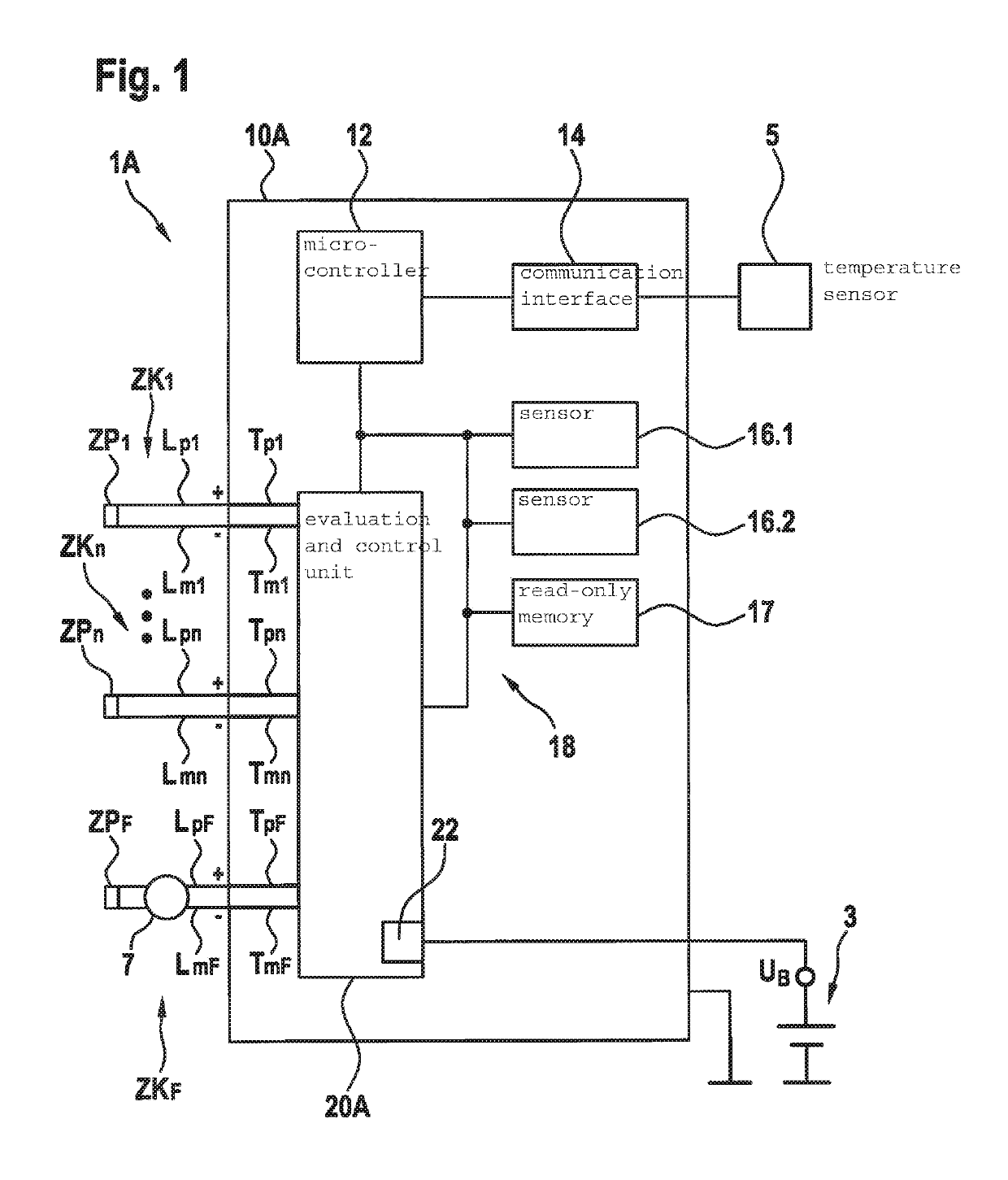
[0008]It is particularly advantageous that the evaluation and control unit reads in the instantaneous temperature in the vehicle interior from a temperature sensor via a communication interface. This advantageously allows for a simple and rapid temperature compensation.
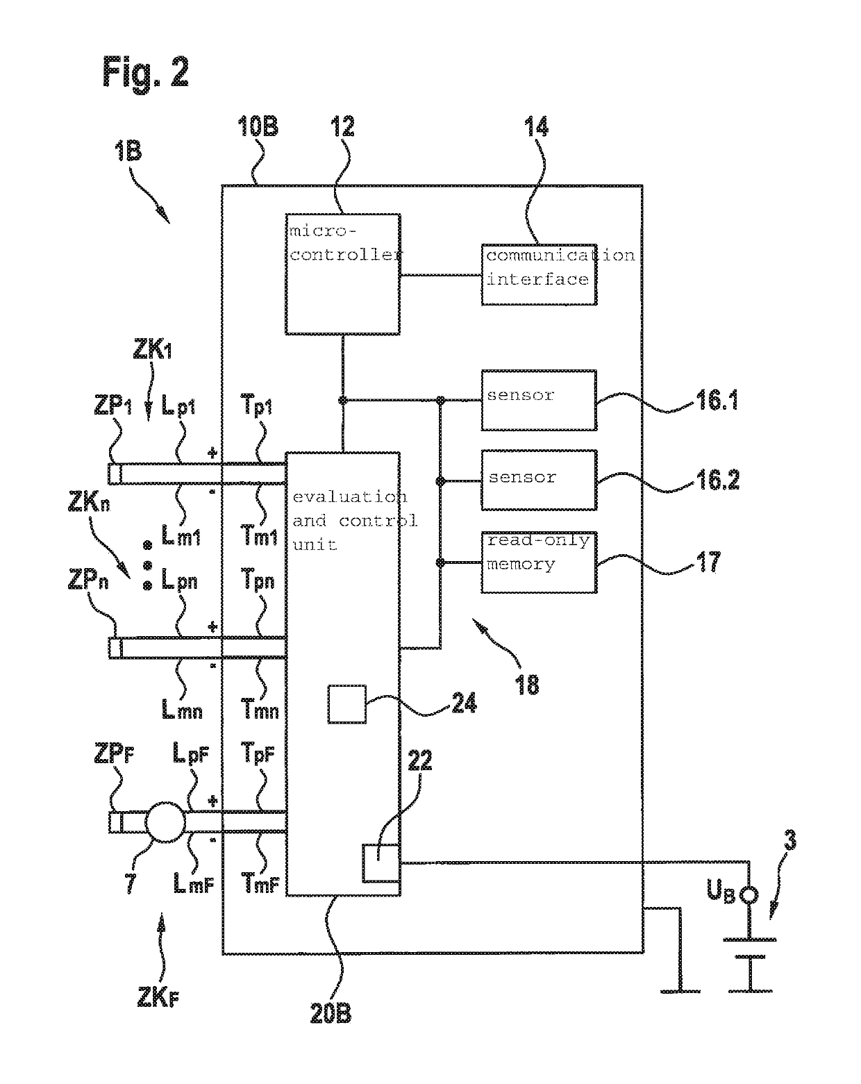
[0009]In one advantageous embodiment of the control unit according to the present invention, the evaluation and control unit may determine an instantaneous internal temperature in the control unit, where the evaluation and control unit may carry out, on the basis of the instantaneous internal temperature in the control unit, a temperature compensation of the ascertained ignition circuit loop resistance for a first conductor which is situated within the control unit and connects the evaluation and control unit to the go-line, and a second conductor which is situated within the control unit and connects the evaluation and control unit to the return line. This advantageously allows for the temperature compensation of the entire feed between the evaluation and control unit and the squib.
[0011]In one further advantageous embodiment of the control unit according to the present invention, a temperature sensor may be situated within the evaluation and control unit, which detects an internal contact temperature within the evaluation and control unit. The evaluation and control unit may advantageously calculate the instantaneous internal temperature in the control unit on the basis of the internal contact temperature and the power loss of the evaluation and control unit and a thermal resistance between the internal contact of the evaluation and control unit and the interior of the control unit. In addition, the evaluation and control unit may calculate the instantaneous temperature in the vehicle interior on the basis of the instantaneous internal temperature in the control unit and the ascertained power losses in the control unit and a thermal resistance of the control unit housing, so that a temperature sensor in the vehicle interior may be dispensed with.

Problems solved by technology

If one of the limiting values is exceeded or fallen below, a faulty state in the ignition circuit is detected.

Method used


Image

  • Control unit for a restraint system in a vehicle
  • Control unit for a restraint system in a vehicle

Examples


Embodiment Construction

[0016]As is apparent from FIGS. 1 and 2, the represented exemplary embodiments of a control unit 10A, 10B according to the present invention for a restraint system in a vehicle each include an evaluation and control unit 20A, 20B and at least one external ignition circuit interface to which a squib ZP1, ZPn, ZPF for activating the restraint system is connected via a go-line Lp1, Lpn, LpF and a return line Lm1, Lmn, LmF. Evaluation and control unit 20A, 20B cyclically ascertains, by measuring, an instantaneous ohmic loop resistance RZK(i)_mess of corresponding ignition circuit ZK1, ZKn, ZKF and compares instantaneous ohmic loop resistance RZK(i)_mess with at least one stored threshold value GO, GU. According to the present invention, evaluation and control unit 20A, 20B determines an instantaneous temperature ϑl in the vehicle interior, close to the time for the measured value detection for ascertaining ignition circuit loop resistance RZK(i)_mess, evaluation and control unit 20A, 20...


PUM


Abstract

A control unit for a restraint system in a vehicle, including an evaluation and control unit and at least one external ignition circuit interface to which a squib for activating the restraint system is connected via a go-line and a return line, the evaluation and control unit cyclically ascertaining, by measuring, an instantaneous ohmic loop resistance of the corresponding ignition circuit and comparing this with at least one stored threshold value. The evaluation and control unit determines an instantaneous temperature in the vehicle interior, close to the time for the measured value detection for ascertaining the ignition circuit loop resistance, the evaluation and control unit carrying out a temperature compensation of the ascertained ignition circuit loop resistance for the go-line and return line of the connected ignition circuit based on the instantaneous temperature in the vehicle interior, the go-line and return line being situated outside the control unit.

Description

FIELD[0001]The present invention is directed to a control unit for a restraint system in a vehicle.BACKGROUND INFORMATION[0002]For the reliable monitoring of ignition circuits for restraint systems in a vehicle, the loop resistance of the ignition circuit is cyclically measured and compared with upper and lower limiting values. If one of the limiting values is exceeded or fallen below, a faulty state in the ignition circuit is detected. Generally, the activation of the airbag warning light takes place only when this faulty state is not the product of a one-time error, but rather is confirmed after suitable filtering.[0003]A circuit for controlling and monitoring ignition circuits in safety devices, such as, for example, restraint systems in motor vehicles, is described in German Patent No. DE 44 32 301 B4. A squib, which is actuatable by an output stage and to which a test current may be applied for continuity testing, is provided in the ignition circuits.SUMMARY[0004]The control un...

Claims


Application Information

Patent Timeline
Patent Type & Authority Patents(United States)
IPC IPC(8): B60R21/017B60R21/01
CPCB60R21/0173B60R2021/01184B60R2021/01136B60R2021/01129
Inventor SCHUMACHER, HARTMUTKOVACIC, LEONARDOGSCHWIND-SCHILLING, RAINERKARNER, RUEDIGER
Owner ROBERT BOSCH GMBH
Why Eureka
Try Eureka