
Printing method and apparatus

a printing method and printing device technology, applied in the field of printing or writing devices, can solve the problems of affecting the clinician's ability to quickly and accurately assess the printed patient data, the practicality of simply reducing the size, and hindering the reduction of the printer size, so as to promote the use of smaller, more portable printing devices without sacrificing the speed, readability, or accuracy of the printout

Inactive Publication Date: 2006-01-03
GE MEDICAL SYST INFORMATION TECH
View PDF12 Cites 39 Cited by
  • Summary
  • Abstract
  • Description
  • Claims
  • Application Information

AI Technical Summary

Benefits of technology

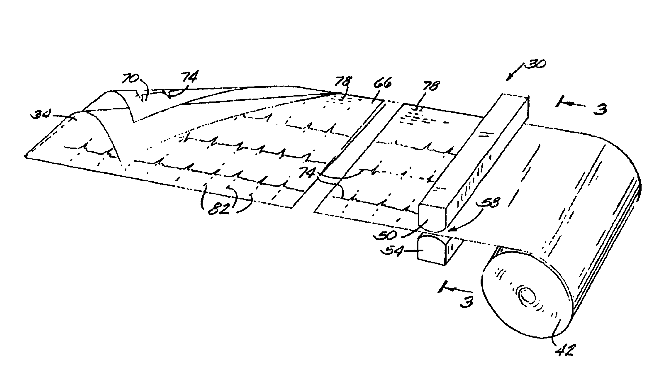
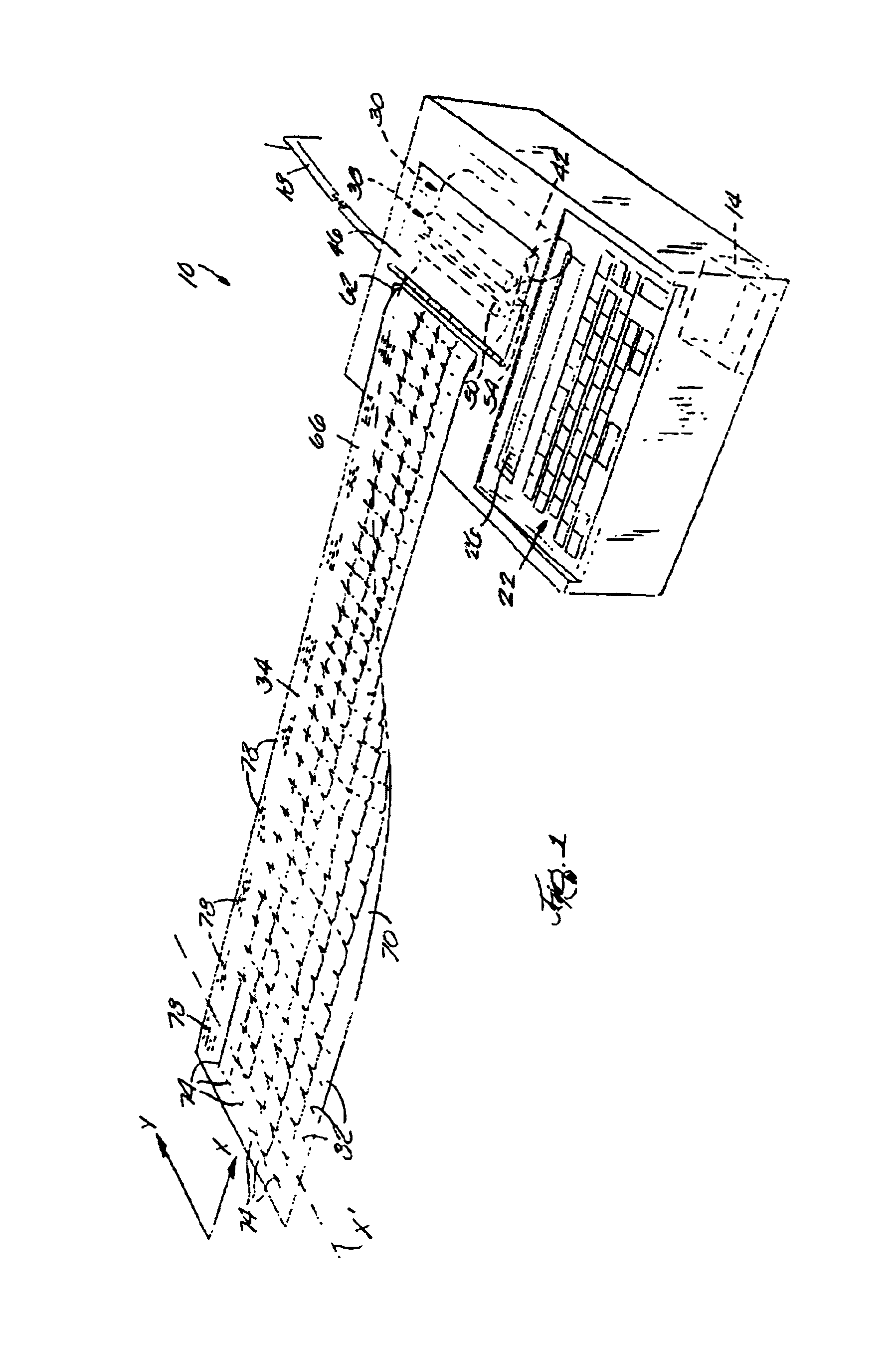
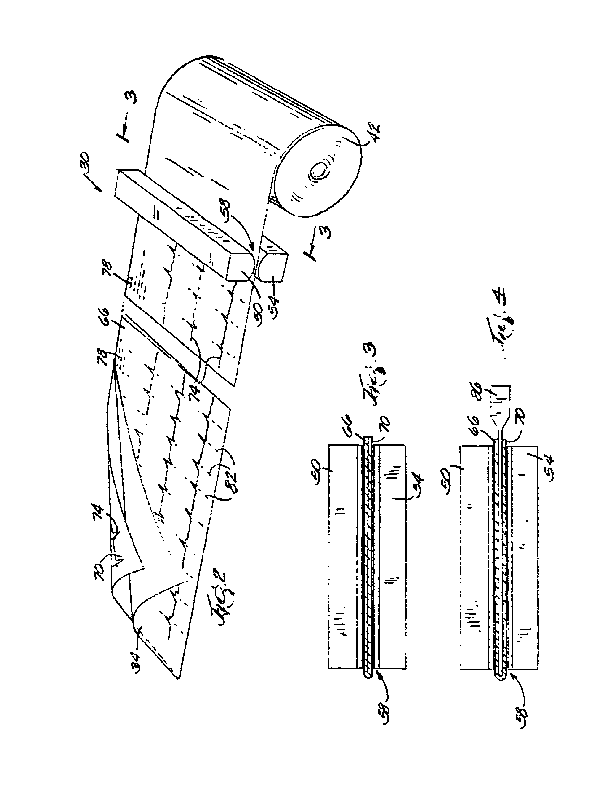
[0006]The present invention overcomes this and other problems by providing an improved printing method and apparatus that promotes the use of smaller, more portable printing devices without sacrificing the speed, readability, or accuracy of the printout. More specifically, the invention provides a method of printing including passing a medium through a printing device and printing on oppositely facing portions of the medium during a single pass of the medium through the printing device. Preferably, printing on oppositely facing portions includes printing on one portion with a first print head and printing on the other portion with a second print head.

Problems solved by technology

While it is desirable to reduce the size of portable medical components (e.g., electrocardiograph (ECG) units, defibrillators, monitors, and the like) there is a concern that reductions in printer size will hinder, and perhaps even impair the clinician's ability to quickly and accurately assess the printed patient data.
Because it is not practical to simply reduce the size of the standard ECG report to fit on this narrower paper (from a practical standpoint, the smaller printout would be difficult and awkward to read, and from a technical standpoint, the standard waveform orientation produced by a 12-lead ECG unit would become severely distorted), it has been known to print the ECG report in halves.
This tearing and realigning process is burdensome and inaccurate and often involves taping or otherwise fastening the halves together.

Method used


Image

  • Printing method and apparatus
  • Printing method and apparatus
  • Printing method and apparatus

Examples


Embodiment Construction

[0016]Before one embodiment of the invention is explained in detail, it is to be understood that the invention is not limited in its application to the details of construction and the arrangements of the components set forth in the following description or illustrated in the drawings. The invention is capable of other embodiments and of being practiced or being carried out in various ways. Also, it is understood that the phraseology and terminology used herein is for the purpose of description and should not be regarded as limiting. The use of “including” and “comprising” and variations thereof herein is meant to encompass the items listed thereafter and equivalents thereof as well as additional items.

[0017]FIG. 1 illustrates a device 10 embodying the invention. In the illustrated embodiment, the device 10 is a portable 12-lead ECG unit, however, the device 10 could be any type of device (medical or non-medical, portable or stationary) used to print data. The device 10 includes a pr...


PUM


Abstract

An apparatus and method for printing on both sides of a medium by passing the medium through a printing device and printing on oppositely facing portions of the medium during a single pass of the medium through the printing device. Preferably, a first print head prints on one portion while a second print head prints on the other portion. The medium is preferably folded so that after the printing is completed and the folded medium is unfolded, the printed information on one portion of the medium correlates with the printed information on the other portion of the medium. The printed information is preferably data that has been measured with respect to time, and the printed data on the oppositely facing portions correlate with respect to time. Preferably, the data is medical patient data in the form of textual data, physiological waveforms, or a combination of both.

Description

BACKGROUND OF INVENTION[0001]Portable printing or writing devices, and more specifically, portable printing devices used in the medical field are known. Typically, portable printing devices are integrated in, or otherwise attached to portable medical devices used to monitor patient data, such as heart rate, blood pressure, blood oxygenation, respiration, brain activity, and the like. The printing devices enable the physician, nurse, medical technician or other healthcare worker (collectively “clinician”) to print a hard copy of the patient data, which can be useful in studying and documenting changes in the patient's condition.SUMMARY OF INVENTION[0002]While it is desirable to reduce the size of portable medical components (e.g., electrocardiograph (ECG) units, defibrillators, monitors, and the like) there is a concern that reductions in printer size will hinder, and perhaps even impair the clinician's ability to quickly and accurately assess the printed patient data. A better under...

Claims


Application Information

Patent Timeline
Patent Type & Authority Patents(United States)
IPC IPC(8): B41J3/60B41J2/32B41J3/54G01D9/00G01D9/40
CPCB41J3/60
Inventor ELKO, PAUL P.BRODNICK, DONALD E.
Owner GE MEDICAL SYST INFORMATION TECH
Learn More