
Vehicle drive apparatus control apparatus

a technology of control apparatus and vehicle, applied in the direction of fluid gearing, transportation and packaging, gearing, etc., to achieve the effect of reducing power loss, reducing size, and suppressing deterioration in fuel efficiency of the vehicl

Active Publication Date: 2015-09-08
TOYOTA JIDOSHA KK
View PDF13 Cites 5 Cited by
  • Summary
  • Abstract
  • Description
  • Claims
  • Application Information

AI Technical Summary

Benefits of technology

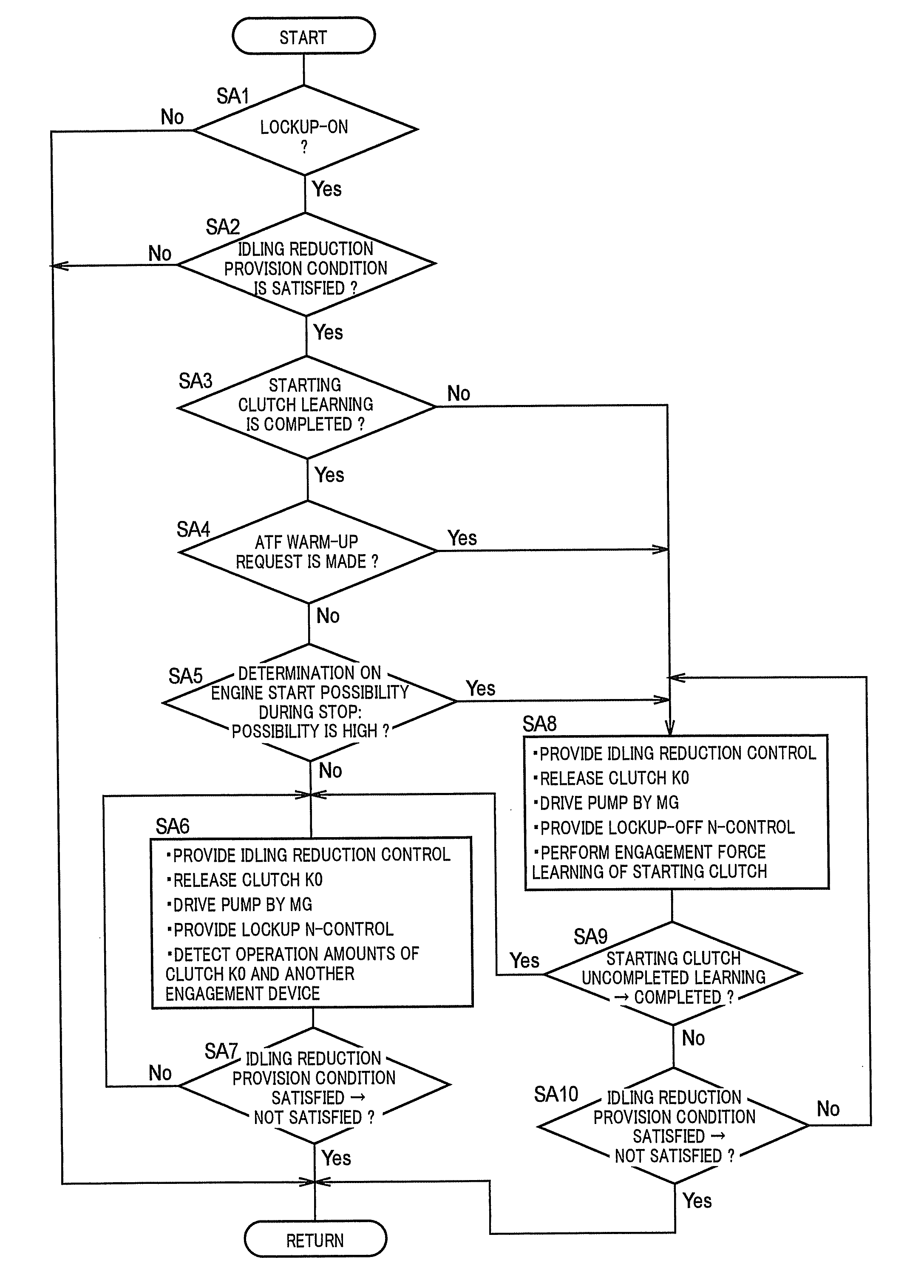
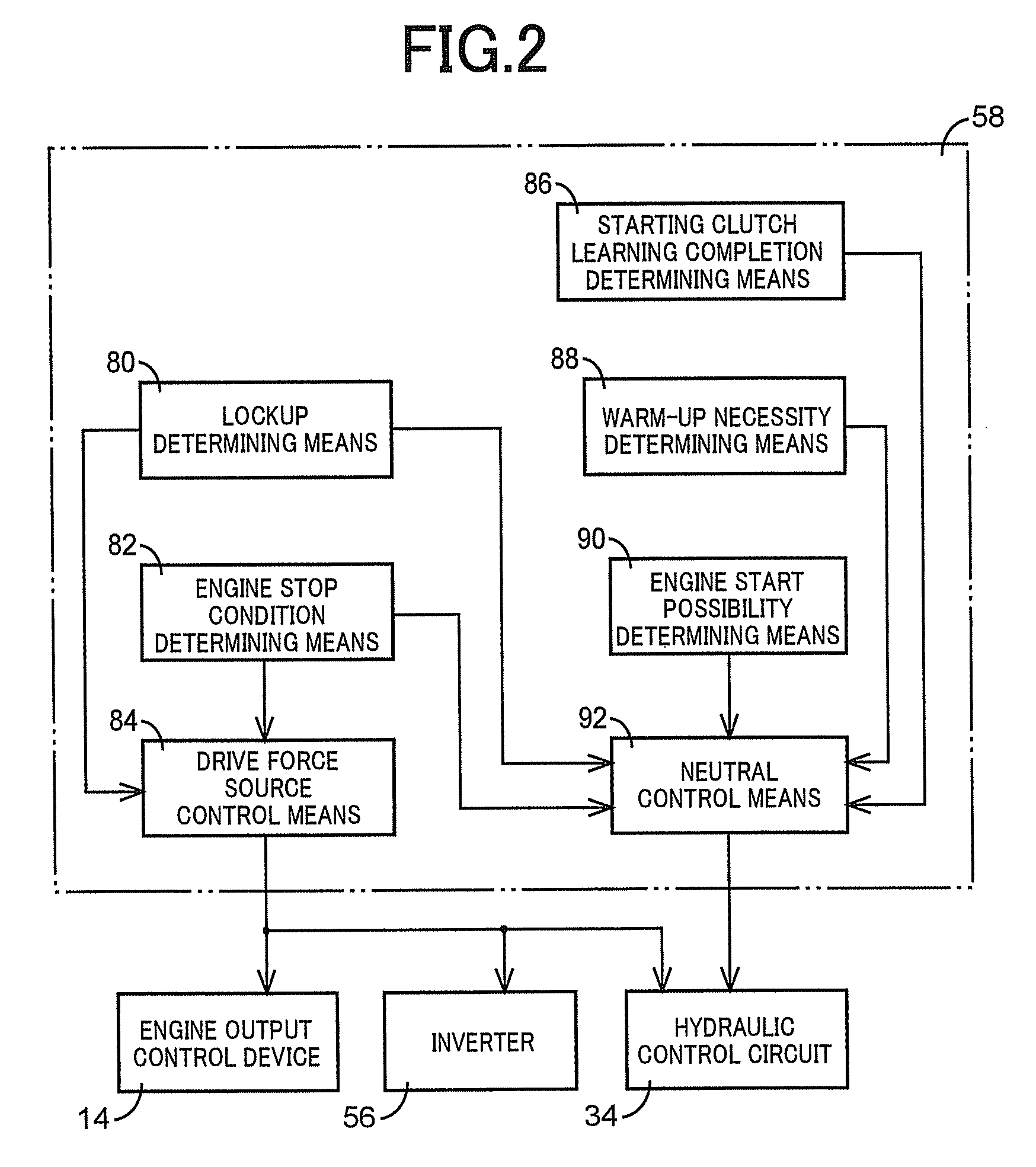
The invention provides a control device for a vehicle drive device that reduces power loss and improves fuel efficiency by executing neutral control during engine stop periods. The control device engages a lockup clutch when the engine is running to mechanically couple input and output members of the hydraulic power transmission device, reducing power loss compared to releasing the lockup clutch during neutral control. The lockup clutch is released during neutral control to prevent transmission of shocks to the drive wheels. The control device also promotes warm-up of the power transmission device by releasing the lockup clutch during neutral control, and detects the operation amount of the engine connecting / disconnecting clutch to improve engine starting responsiveness and suppress engagement shock.

Problems solved by technology

If an abnormality occurs in the electric oil pump, the control device of the vehicle drive device drives the mechanical oil pump by the electric motor to generate oil pressure.

Method used


Image

  • Vehicle drive apparatus control apparatus
  • Vehicle drive apparatus control apparatus
  • Vehicle drive apparatus control apparatus

Examples


example

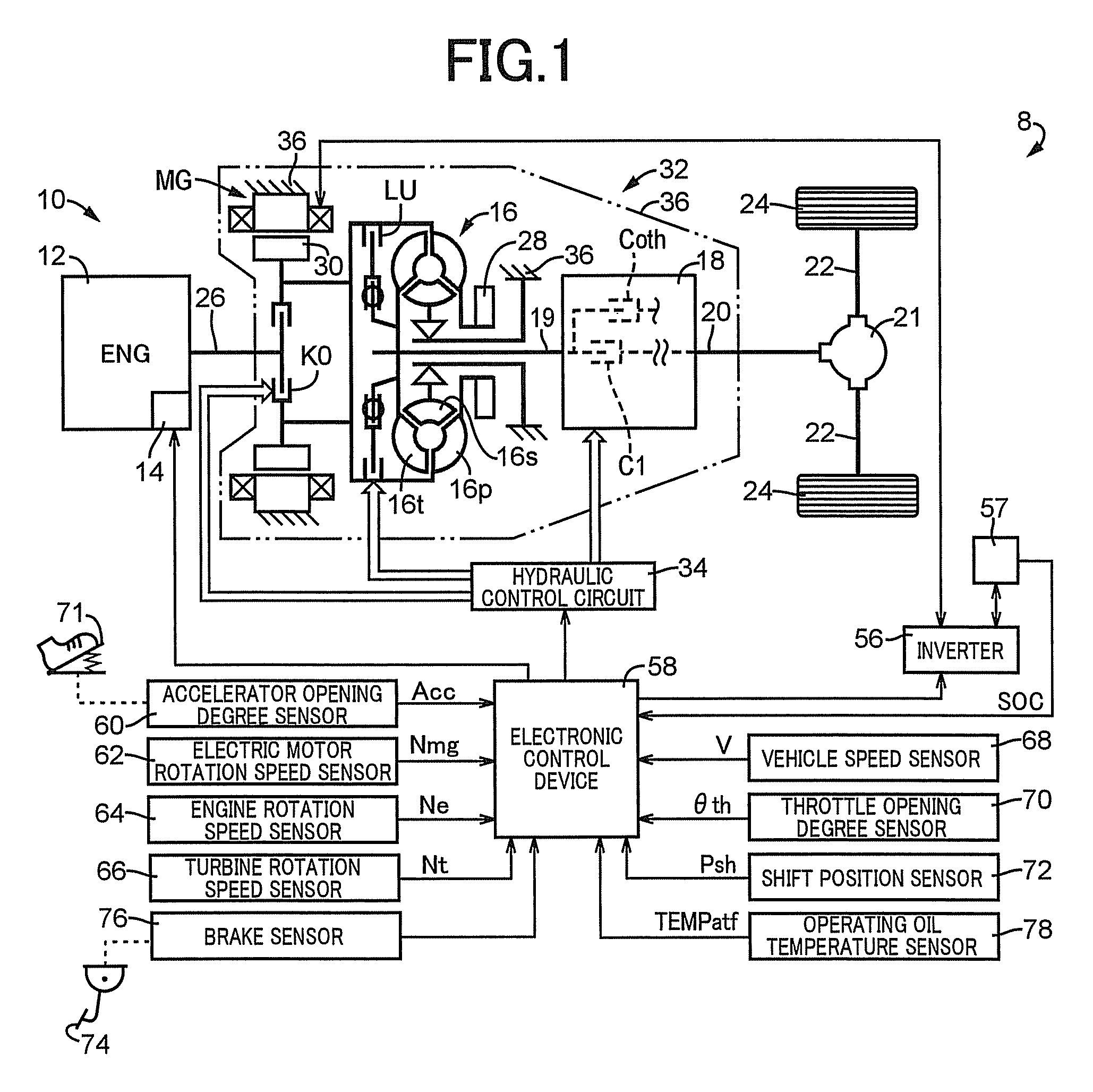
[0028]FIG. 1 is a conceptual diagram of a configuration of a drive system according to a hybrid vehicle 8 (hereinafter simple referred to as a “vehicle 8”) that is an example of the present invention. The hybrid vehicle 8 depicted in FIG. 1 includes a vehicle drive device 10 (hereinafter referred to as a “drive device 10”), a differential gear device 21, a pair of left and right axles 22, a pair of left and right drive wheels 24, a hydraulic control circuit 34, an inverter 56, and an electronic control device 58. The drive device 10 includes an engine 12 such as a known gasoline engine and diesel engine acting as a drive force source for running, an engine output control device 14 starting or stopping the engine 12 and executing engine output control such as throttle control, an electric motor MG that is an electric motor for running acting as a drive force source for running, an engine connecting / disconnecting clutch K0, a torque converter 16, an automatic transmission 18, and a me...


PUM


Abstract

A control device of a vehicle drive device includes a mechanical oil pump, a hydraulic power transmission device transmitting power of the engine and the electric motor to drive wheels via an interposed engagement device when it is engaged. While the electric motor drives the mechanical oil pump while an operation of the engine is stopped, the control device executing neutral control of putting the engagement device into a slip state or released state to suppress power transmission between the hydraulic power transmission device and the drive wheels, the hydraulic power transmission device including a lockup clutch mechanically coupling input and output members of the hydraulic power transmission device when engaged, the lockup clutch being engaged during executing of the neutral control. Also, after it is determined that the engine is likely to be restarted after a stop of operation while the vehicle remains stopped, the lockup clutch being released.

Description

CROSS-REFERENCE TO RELATED APPLICATIONS[0001]This is a national phase application based on the PCT International Patent Application No. PCT / JP2011 / 073447 filed on Oct. 12, 2011, the entire contents of which are incorporated herein by reference.TECHNICAL FIELD[0002]The present invention relates to control executed when a hybrid vehicle stops.BACKGROUND ART[0003]A hybrid vehicle is conventionally known that has an engine, an electric motor, and a mechanical oil pump coupled sequentially in series so as to run by power of at least one of the engine and the electric motor. For example, a control device of a vehicle drive device included in the hybrid vehicle is disclosed in Patent Document 1. The vehicle drive device of Patent Document 1 includes an electric oil pump. If an abnormality occurs in the electric oil pump, the control device of the vehicle drive device drives the mechanical oil pump by the electric motor to generate oil pressure.PRIOR ART DOCUMENTSPatent Documents[0004]Paten...

Claims


Application Information

Patent Timeline
Patent Type & Authority Patents(United States)
IPC IPC(8): F16H61/14B60W20/00B60W30/18F16D48/02B60K6/48B60W10/02B60L50/16
CPCF16H61/14B60K6/48B60W10/02B60W20/00B60W30/18063F16D48/02B60Y2300/429Y02T10/6221Y02T10/6295Y10S903/946Y02T10/62F16H2061/207F16H61/143F16H61/0025B60Y2300/18016B60W10/30B60W10/10B60W20/40
Inventor ETO, SHINGOKOBAYASHI, NOBUFUSAIDESHIO, YUKIHIKO
Owner TOYOTA JIDOSHA KK
Learn More