
Welding arc apparel with UV or thermochromic activated images

a technology of welding arc and apparel, applied in the field of welding accessories, can solve the problems of indirect exposure, retinal injury, and other health hazards, and the uv radiation produced by the electric welding arc is capable of causing injury comparable to sunburn,

Active Publication Date: 2015-09-01
LINCOLN GLOBAL INC
View PDF37 Cites 1 Cited by
  • Summary
  • Abstract
  • Description
  • Claims
  • Application Information

AI Technical Summary

Benefits of technology

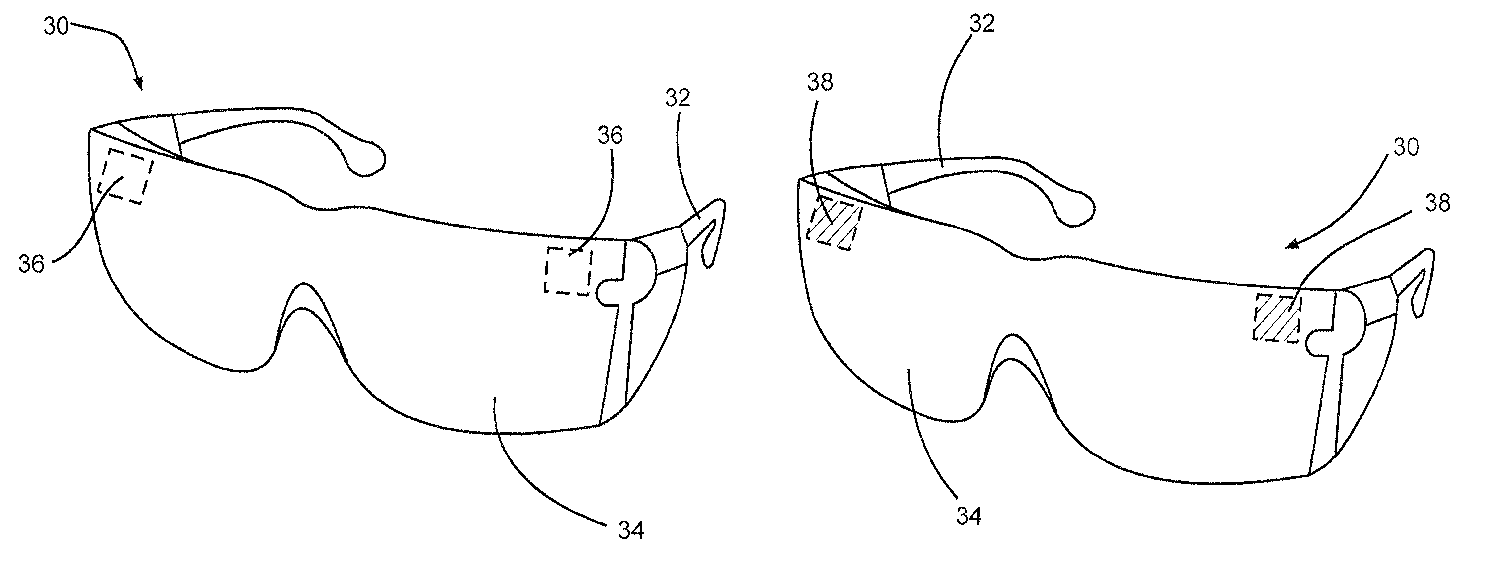
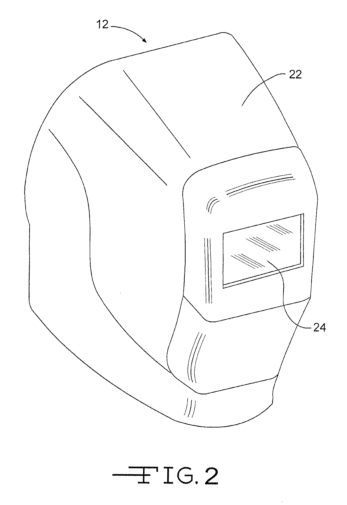
The present invention relates to welding accessories that can visually indicate the presence of UV (ultraviolet) radiation and thermal (heat) energy generated by an electric welding arc during a welding operation. The indication may be a permanent or reversible transition between two images. The accessories may include welding helmets, jackets, gloves, safety glasses, indicator badges, work boots, belts, and jewelry, among others. The visual indication is achieved using UV activated dyes, pigments, or inks that react to the UV radiation or thermochromic dyes, pigments, or paints that change color upon exposure to heat. The indication may include various symbols, logos, text, or images to indicate the presence or absence of UV or heat exposure. The system can also detect cumulative UV radiation exposure or cumulative heat exposure during welding operations using the UV exposure indicator or thermochromic exposure indicator with graduated states.

Problems solved by technology

The UV radiation produced by the electric welding arc is capable of causing injury comparable to a sun burn.
In addition to direct exposure to UV radiation, UV radiation can reflect from surfaces common in a welding environment, such as unpainted metals and concrete floors, resulting in indirect exposure.
Further, the effects of UV radiation exposure are cumulative and repeated exposure can result in retinal injury and other health hazards.
The produced thermal (heat) radiation may equally be detrimental to the welder, and excess amounts can be reflective of improper setup of the welding operation, or improper welding technique or a myriad of other technical and / or user-related issues.
The reflection of UV radiation from unpainted metal, concrete, and other surfaces however limits the effectiveness of shielding the welding operation.
Welding operations have also been located away from walkways, aisles, and other areas where other personnel are working to reduce exposure to the other personnel, however, this is often impractical when welding operations are conducted in confined areas.

Method used


Image

  • Welding arc apparel with UV or thermochromic activated images
  • Welding arc apparel with UV or thermochromic activated images
  • Welding arc apparel with UV or thermochromic activated images

Examples


Embodiment Construction

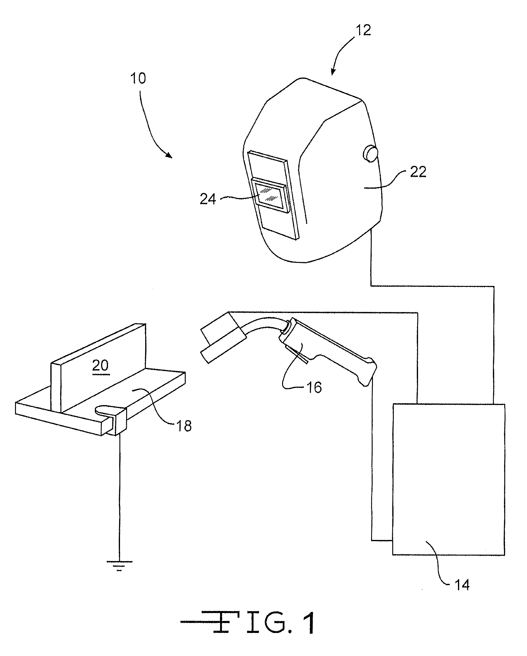
[0021]Referring now to the drawings, FIG. 1 illustrates a welding environment 10. The welding environment 10 includes welding helmet 12, welding system 14, welding gun 16, and workpiece 18. The welding environment may also, for example, include a stick electrode holder, TIG torch or other apparatus for use with electric arc welding. Workpiece 18 generally defines a welding work area 20 where the welding gun may be used to form a weld. Various non-limiting types of exemplary welding, including Shielded Metal Arc Welding (SMAW), Gas Metal Arc Welding (GMAW) e.g. MIG melding, and Gas Tungsten Arc Welding (GTAW) e.g. TIG welding, may be conducted in the welding environment.

[0022]Welding system 14 includes welding equipment for generating a welding current and voltage, a welding control system for controlling the welding current and voltage, and a monitoring system for monitoring the welding current and voltage. The monitoring system may also monitor a variety of other operating paramete...


PUM

PropertyMeasurementUnit
wavelengthaaaaaaaaaa

Abstract

A welding accessory and a system for detecting thermal and / or UV radiation exposure during welding operations are disclosed. The welding accessory may have a surface exposed to thermal and / or UV radiation generated by electric arc welding, a first image visible without exposure to the thermal and / or UV radiation, and a second image formed from either a UV activated dye that is visible only after exposure to UV radiation generated by the electric welding arc or a thermochromic dye that is visible only after exposure to a predetermined level of thermal radiation generated by the welding arc. A system may include either a thermal or UV exposure indicator with a first state and at least a second state, and include either a thermochromic or UV activated dye adapted to provide a reversible or persistent visual indication upon exposure to radiation. The visual indication may include any combination of symbols, logos, images, text, or other decorative or informational designs as desired.

Description

CROSS-REFERENCE TO RELATED APPLICATIONS[0001]This application claims priority from U.S. patent application Ser. No. 12 / 618,231 filed on 13 Nov. 2009, the application being hereinby fully incorporated by reference.TECHNICAL FIELD OF THE INVENTION[0002]The present disclosure relates to welding accessories, and more specifically, to welding apparel with images activated by UV radiation from an electric welding arc or with images activated at various welding exposure temperatures.BACKGROUND OF THE INVENTION[0003]Welding is an important process in the manufacture and construction of various products and structures. Applications for welding are widespread and used throughout the world including, for example, the construction and repair of ships, buildings, bridges, vehicles, and pipe lines, to name a few. Welding is performed in a variety of locations, such as in a factory with a fixed welding operation or on site with a portable welder.[0004]In manual or semi-automated welding a user / ope...

Claims


Application Information

Patent Timeline
Patent Type & Authority Patents(United States)
IPC IPC(8): G01K11/00G01K11/12A61F9/06F16P1/06G01J1/58G01J1/42C09D11/50B23K9/32
CPCG01K11/12A61F9/067B23K9/322C09D11/50F16P1/06G01J1/429G01J1/58
Inventor CHANTRY, BRUCE JOHNMCDOWELL, MARK DAVID
Owner LINCOLN GLOBAL INC
Learn More