
Process for producing nano graphene reinforced composite particles for lithium battery electrodes

a technology of graphene reinforced composite particles and lithium batteries, which is applied in the direction of active material electrodes, cell components, transportation and packaging, etc., can solve the problems of high cost, inability to produce at a high rate in large quantities, and high cost, so as to enhance the structural integrity of the carbon matrix, reduce the amount of carbon material, and reduce the site of amorphous carbon

Active Publication Date: 2015-07-28
SAMSUNG ELECTRONICS CO LTD
View PDF13 Cites 19 Cited by
  • Summary
  • Abstract
  • Description
  • Claims
  • Application Information

AI Technical Summary

Benefits of technology

[0067]For the purpose of increasing the strength, stiffness, and fracture toughness of a protective matrix (such as carbon) to maintain the structural integrity of an electrode (either anode or cathode), presumably one can make use of carbon nano-tubes (CNTs) as a primary nano reinforcement additive since CNTs are known to have high strength and stiffness. However, at this stage of development, CNTs are extremely expensive and cannot be produced at a high rate in large quantities. The high costs associated with NGPs have been the primary reason responsible their limited uses in industry thus far.
[0070]For instance, Jang, et al. [Ref. 33] disclosed a process to readily produce NGPs in large quantities. The process includes the following procedures: (1) providing a graphite powder containing fine graphite particles preferably with at least one dimension smaller than 200 μm (most preferably smaller than 1 μm); (2) exfoliating the graphite crystallites in these particles in such a manner that at least two graphene planes are fully separated from each other, and (3) mechanical attrition (e.g., ball milling) of the exfoliated particles to become nano-scaled, resulting in the formation of NGPs with platelet thickness smaller than 100 nm. The starting powder type and size, exfoliation conditions (e.g., intercalation chemical type and concentration, temperature cycles, and the mechanical attrition conditions (e.g., ball milling time and intensity) can be varied to generate, by design, various NGP materials with a wide range of graphene plate thickness, width and length values. We have successfully prepared NGPs with an average length in the range of 0.5 to 10 μm). However, the length or width can be smaller than 500 nm and, in several cases, smaller than 100 nm. Ball milling is known to be an effective process for mass-producing ultra-fine powder particles. The processing ease and the wide property ranges that can be achieved with NGP materials make them promising candidates for many important engineering applications. The electronic, thermal and mechanical properties of NGP materials are comparable to those of carbon nano-tubes; but NGPs are now available at much lower costs and in larger quantities. Again, NGPs are a new, emerging class of nano materials that are distinct and different from CNTs.
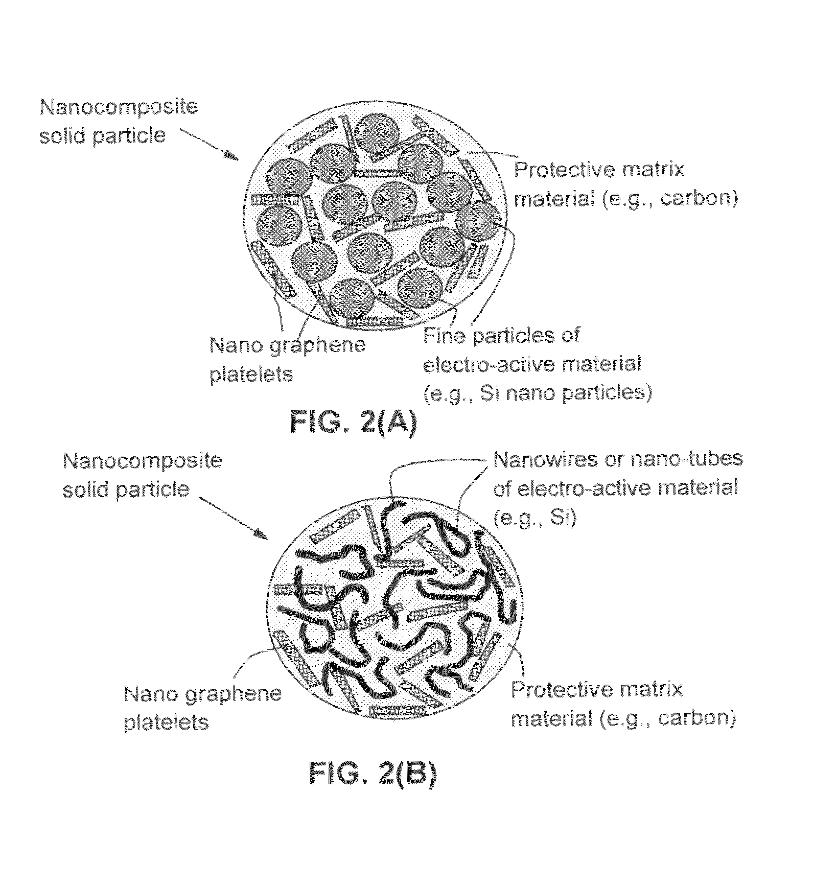
[0072]After extensive and in-depth research and development efforts, we came to realize that NGPs (particularly those with a thickness <10 nm, preferably <1 nm) are very effective in enhancing the mechanical properties of a protective matrix (such as amorphous carbon or polymeric carbon, polymer, and metal oxide) in a lithium battery electrode. NGP-reinforced protective matrix materials are capable of cushioning the stresses-strains induced to an electro-active particle during lithium insertion and extraction (discharge and charge) cycles. Surprisingly, NGPs were found to significantly enhance the structural integrity (strength and fracture resistance) of a range of protective matrix materials for electrodes, to the extent that a high specific capacity was maintained over a much larger number of cycles compared with those electrodes without an NGP-reinforced protective matrix.
[0076]The matrix material may be selected from a polymer, polymeric carbon, amorphous carbon, meso-phase carbon, coke, petroleum pitch, coal tar pitch, meso-phase pitch, metal oxide, metal hydride, metal nitride, metal carbide, metal sulfide, ceramic, inorganic, organic material, or a combination thereof. Preferably, the protective matrix material comprises a carbon material obtained by pyrolyzing or heat-treating a polymer, monomer, organic material, coal tar pitch, petroleum pitch, meso-phase pitch, sugar, glucose, or a combination thereof. The carbon material is lithium ion-conducting. The amount of this carbon material is preferably reduced by adding a controlled amount of NGPs dispersed therein. The NGPs serve to reduce the sites in amorphous carbon that otherwise could irreversibly trap lithium ions or atoms and significantly enhance the structural integrity of the carbon matrix.
[0077]Typically, the obtained nanocomposite solid particles are substantially spherical or ellipsoidal in shape and are of approximately 1-20 μm in size (preferably and usually smaller than 5 μm in diameter or long axis). For the preparation of an electrode (e.g., anode), these nanocomposite solid particles are then bonded together with a binder material (e.g., styrene-butadiene rubber, SBR, poly(tetrafluoroethylene), PTFE, or poly(vinylidene fluoride), PVDF), a procedure similar to the standard procedure in the current practice of making lithium ion batteries. These nanocomposite particles are superior to meso-carbon micro-beads (MCMBs), conventional fine graphite particles, and conventional graphite spherules when used as an anode active material for a lithium ion battery. The presently invented solid nanocomposite particles can be readily mass-produced and are of low cost. Solid particles can be readily made to be smaller than 5 μm if the length / width of NGPs chosen are smaller than 2 or 3 μm in size and the electro-active material particles (in a particulate, wire, rod, tube, or filament form) have a diameter <1 μm. When used as an anode active material, they exhibit a high reversible capacity, a low irreversible capacity, good compatibility with commonly used electrolytes (no graphite layer exfoliation phenomenon and no active material-electrolyte reaction), and a long charge-discharge cycle life.
[0080]The NGPs preferably have a thickness less than 100 nm, and a length, width, or diameter less than 10 μm. The thickness is more preferably less than 10 nm and most preferably less than 1 nm. The length, width, or diameter of NGPs is preferably less than 5 μm (more preferably smaller than 2 μm) so that the composite solid particles are typically no greater than 10 μm in diameter (preferably smaller than 5 μm). This will allow for facile migration of lithium ions, enabling a high-rate capacity.

Problems solved by technology

However, at this stage of development, CNTs are extremely expensive and cannot be produced at a high rate in large quantities.
The high costs associated with NGPs have been the primary reason responsible their limited uses in industry thus far.

Method used


Image

  • Process for producing nano graphene reinforced composite particles for lithium battery electrodes
  • Process for producing nano graphene reinforced composite particles for lithium battery electrodes
  • Process for producing nano graphene reinforced composite particles for lithium battery electrodes

Examples


example 1

Preparation of NGPs of Various Sizes from Natural Graphite and Production of Corresponding NGP-Reinforced Solid Nanocomposite Particles

[0136]Natural flake graphite, nominally sized at 45 μm, provided by Asbury Carbons (405 Old Main St., Asbury, N.J. 08802, USA) was milled to reduce the size to approximately 14 μm. The chemicals used in the present study, including fuming nitric acid (>90%), sulfuric acid (95-98%), potassium chlorate (98%), and hydrochloric acid (37%), were purchased from Sigma-Aldrich and used as received. Graphite intercalation compounds (GICs), which were actually highly oxidized graphite or graphite oxide (GO) samples, were prepared according to the following procedure:

[0137]In a typical procedure, a reaction flask containing a magnetic stirring bar was charged with sulfuric acid (1.76 L) and nitric acid (0.90 L) and cooled by immersion in an ice bath. The acid mixture was stirred and allowed to cool for 20 min, and graphite (100 g) was added under vigorous stirr...

example 2

Cycling Behaviors of NGP-Containing Nanocomposite, NGP-Free Nanocomposite, and Graphite-Filled Nanocomposite Solid Particle-Based Anodes (all Containing Si Nano Particles)

[0141]In Example 1, a series of samples containing different weight fractions of Si nano particles (2% to 90%) and different weight fractions of NGPs (2% to 90%) in a carbon matrix (5% to 60%) were prepared.

[0142]One of the samples prepared contains approximately 15% NGPs, 60% Si nano particles, and 25% carbon matrix and is herein designated as Sample 1. For comparison purpose, a Comparative Sample 1a was prepared by dispersing Si nano particles (approximately 70%) in a pitch matrix, as in Sample 1 but without the presence of the NGP. A Comparative Sample 1b was prepared by replacing NGPs with fine natural graphite particles (average diameter=3.5 μm) obtained by air-jet milling of natural flake graphite. FIG. 5 shows the half-cell cycling behaviors of Sample 1, Comparative Sample 1a, and Comparative Sample 1b. It i...

example 3

NGP Reinforced Nanocomposite Solid Particles (NGPs Prepared from Other Laminar Graphite Materials)

[0144]NGPs of Samples 3A, 3B, 3C, and 3D were prepared according to the same procedure used for Sample 1, but the starting graphite materials were highly oriented pyrolytic graphite (HOPG), graphite fiber (Amoco P-100), graphitic carbon nano-fiber (from Applied Sciences, Inc., Cedarville, Ohio), and spheroidal graphite (from Hua Dong Graphite Co., Pingdu, China), respectively. Their final interplanar spacings, according to x-ray diffraction data, prior to exfoliation and separation, were 6.6 Å, 7.3 Å, 7.3 Å, and 6.6 Å, respectively. They were exposed to an exfoliation temperature of 950° C. for 45 seconds, followed by a mechanical shearing treatment using a Cowles rotating-blade apparatus for 30 minutes. The resulting suspensions or slurries were then subjected to a drying treatment to obtain NGPs.

[0145]The NGPs, along with various proportions of nano Si particles and SnO particles, wer...


PUM

PropertyMeasurementUnit
thicknessaaaaaaaaaa
thicknessaaaaaaaaaa
thicknessaaaaaaaaaa

Abstract

A process for producing solid nanocomposite particles for lithium metal or lithium ion battery electrode applications is provided. In one preferred embodiment, the process comprises: (A) Preparing an electrode active material in a form of fine particles, rods, wires, fibers, or tubes with a dimension smaller than 1 μm; (B) Preparing separated or isolated nano graphene platelets with a thickness less than 50 nm; (C) Dispersing the nano graphene platelets and the electrode active material in a precursor fluid medium to form a suspension wherein the fluid medium contains a precursor matrix material dispersed or dissolved therein; and (D) Converting the suspension to the solid nanocomposite particles, wherein the precursor matrix material is converted into a protective matrix material reinforced by the nano graphene platelets and the electrode active material is substantially dispersed in the protective matrix material. For a lithium ion battery anode application, the matrix material is preferably amorphous carbon, polymeric carbon, or meso-phase carbon. Such solid nanocomposite particles provide a high anode capacity and good cycling stability. For a cathode application, the resulting lithium metal or lithium ion battery exhibits an exceptionally high cycle life.

Description

FIELD OF THE INVENTION[0001]The present invention provides a process for making a nano graphene reinforced composite particle material for use in a lithium ion battery electrode (anode or cathode) or in a lithium metal cathode.BACKGROUND[0002]The description of the prior art will be primarily based on the list of references presented at the end of this section. For convenience, the references will be cited with a numerical xx enclosed in a square bracket, [Ref. xx] or simply [xx].[0003]Concerns over the safety of earlier lithium secondary batteries led to the development of lithium ion secondary batteries, in which pure lithium metal sheet or film was replaced by carbonaceous materials as an anode. There are three fundamentally distinct types of carbonaceous anode materials: (a) graphite, (b) amorphous carbon, and (c) graphitized carbon.[0004]The first type of carbonaceous material includes primarily natural graphite and synthetic graphite (or artificial graphite, such as highly ori...

Claims


Application Information

Patent Timeline
Patent Type & Authority Patents(United States)
IPC IPC(8): H01M4/02H01M4/62H01M4/587H01M4/58H01M4/525H01M4/505H01M4/485H01M4/38H01M4/1395H01M4/1391H01M10/052
CPCH01M4/1391H01M4/1395H01M4/38H01M4/485H01M4/505H01M4/525H01M4/587H01M4/5825H01M4/62H01M4/625H01M10/052Y02E60/122Y02T10/7011H01M4/386H01M4/387Y02E60/10Y02T10/70
Inventor ZHAMU, ARUNAJANG, BOR Z.SHI, JINJUN
Owner SAMSUNG ELECTRONICS CO LTD
Learn More