Belt splicing apparatus for conveyor belts

Active Publication Date: 2015-07-28
FLEXIBLE STEEL LACING
View PDF53 Cites 24 Cited by
  • Summary
  • Abstract
  • Description
  • Claims
  • Application Information

AI Technical Summary

Benefits of technology

The present patent describes a belt splicing apparatus that uses a thin sheet plate to heat and melt the belt material in overlying engagement with the belt ends. The metallic material of the thin sheet plate helps to maintain a uniform temperature and prevents the belt material from solidifying too quickly. The apparatus is portable, self-contained, and does not require additional equipment or external pneumatic or hydraulic supplies for operation. It includes a fan device for cooling the platens and an on-board control system for regulating the temperature of the platens. The heating device has an elongate configuration and includes walls that direct air to cool the heating mechanism and the belt ends, allowing for rapid cooling without the need for an external pneumatic or hydraulic hookup.

Problems solved by technology

Despite the stiffness of these steel press plates, they were found to undergo substantial and unacceptable permanent deformation under operational conditions after undergoing several cycles of heating and cooling.
However, it has been found that the platen is able to resist becoming permanently deformed despite the fact that the predetermined material has a lower modulus of elasticity and stiffness than stainless steel and therefore is less able to restrict deflection upon operation of a pressure device that drives the lower platen against the belt ends than the previously used stainless steel press plates.
This is particularly problematic, because the heated center portion would undergo greater expansion than the cooler adjacent edge portions, so that substantial strains were formed in the transition area therebetween.

Method used


Image

  • Belt splicing apparatus for conveyor belts
  • Belt splicing apparatus for conveyor belts
  • Belt splicing apparatus for conveyor belts

Examples


Embodiment Construction

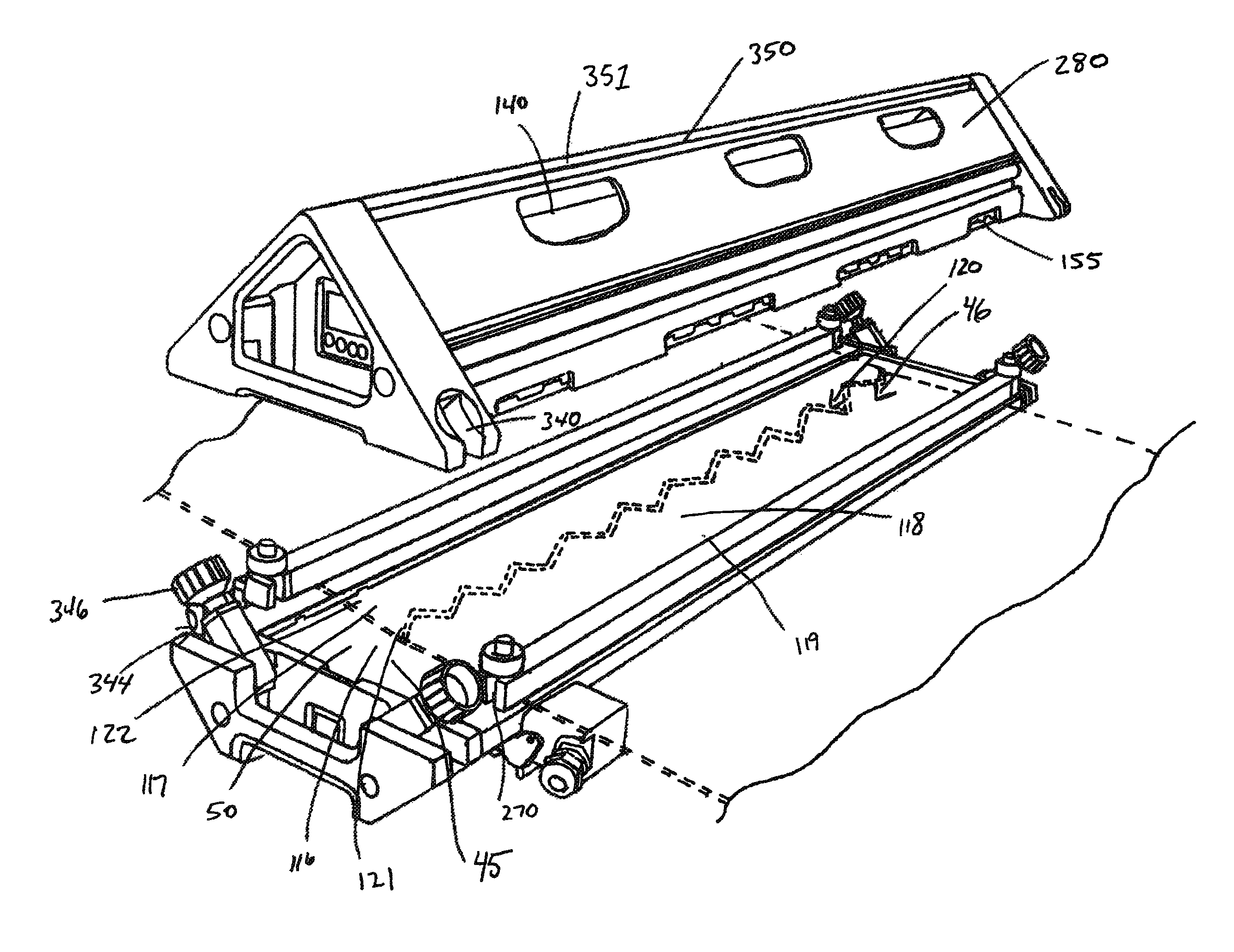
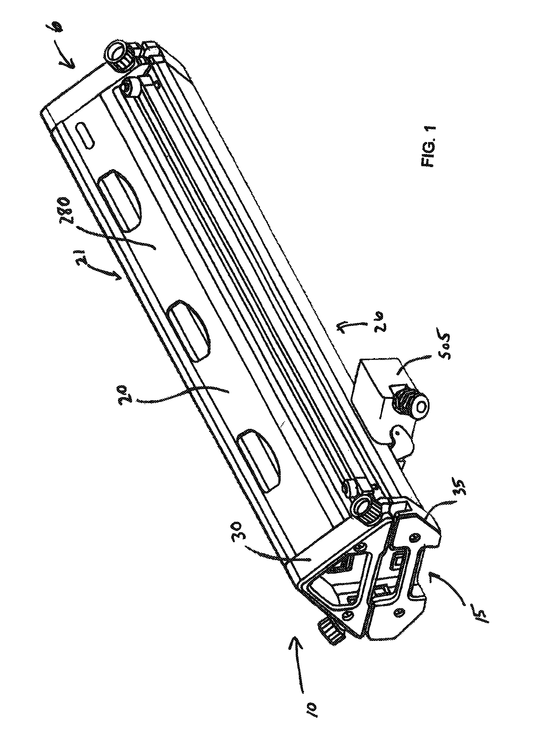
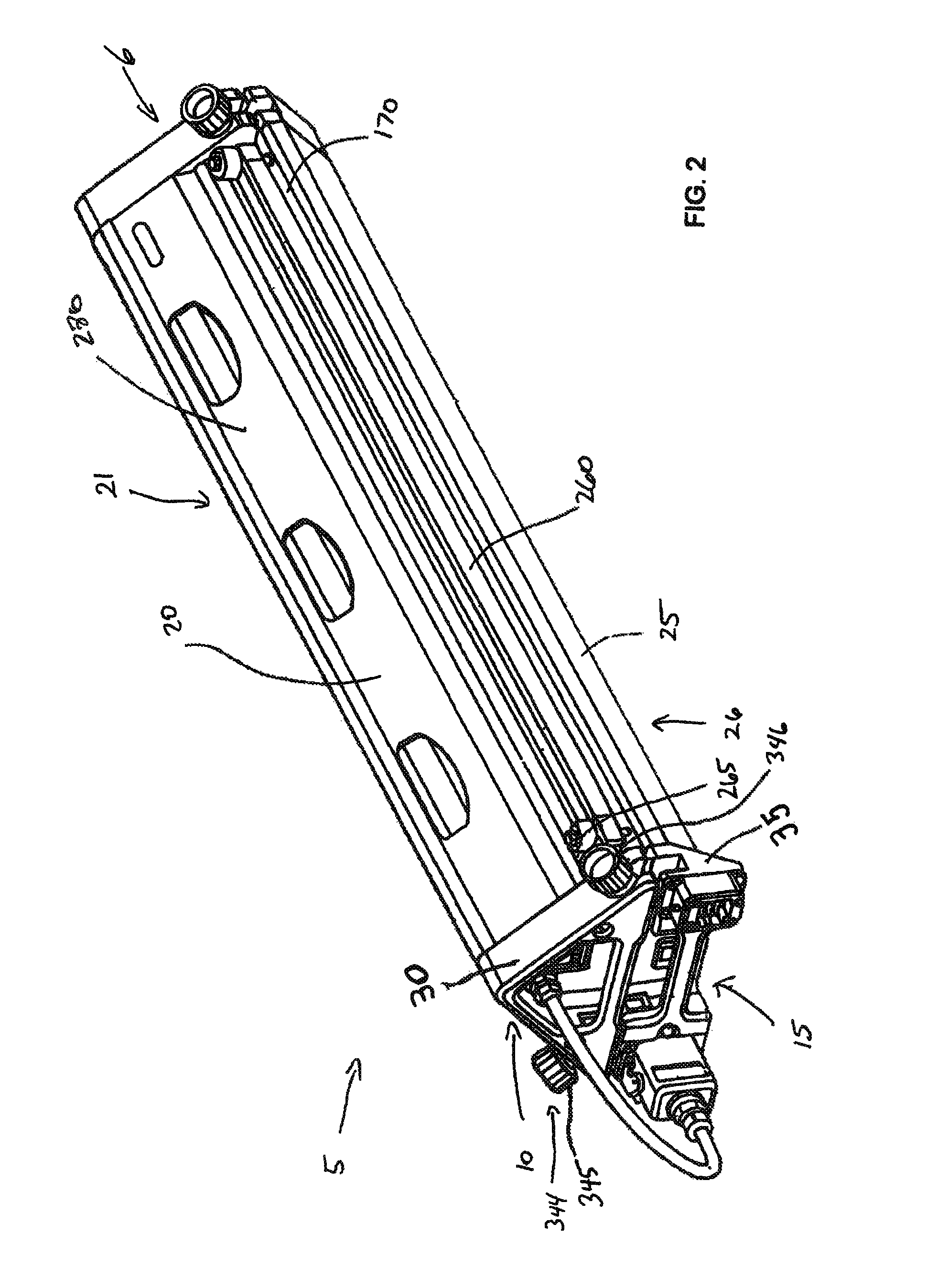
[0065]In FIG. 1-3 a portable belt splicing apparatus or splice press apparatus 5 in accordance with one form of the invention is illustrated, which includes a housing assembly 6 having upper and lower press assemblies 10 and 15 formed generally from upper and lower elongate frames 20 and 25 of lightweight extruded material and end walls 30 and 35 to form upper and lower frame portions or housing frames 21 and 26. In one approach, shown in FIGS. 1, 3 and 6 the upper and lower press assemblies 10 and 15 include corresponding oppositely facing upper and lower platens 40 and 45 that are mounted to the upper and lower frame portions 20 and 25. During operation, the belt ends 46 to be joined are supported by an upper press surface 50 of the lower platen 45 and are clamped between the upper press surface 50 and a lower press surface 55 of the upper platen 40 as illustrated in FIG. 6.

[0066]A heating device is arranged for heating at least one of the upper and lower platens 40 and 45 at an e...


PUM

PropertyMeasurementUnit
Temperatureaaaaaaaaaa
Lengthaaaaaaaaaa
Forceaaaaaaaaaa

Abstract

A portable belt splicing apparatus is provided for joining the ends of one or more conveyor belts together. In one form, the belt splicing apparatus has upper and lower platens, with one formed of a metallic material that allows for operational deflection of the platens under elevated operation pressures while resisting permanent deformation upon being subjected to elevated operation temperatures. An elongate central region of the platens is heated by a heating element and the metallic material restricts the flow of heat from the elongate central region to elongate side edge portions so that the side edge portions remain cooler. In another form, a self-contained portable conveyor belt splicing apparatus is provided having an on-board fan device for rapid cooling of the clamped belt end and platens. An on-board control system is configured to receive power from different types of standard power supplies and supplies power to on-board components.

Description

CROSS REFERENCES TO RELATED APPLICATIONS[0001]This patent claims benefit under 35 U.S.C. §119 (e) to U.S. Provisional Application No. 61 / 243,415 entitled “Splice Press Apparatus for Conveyor Belts” filed Sep. 17, 2009, the contents of which are incorporated herein by reference in its entirety.FIELD OF THE INVENTION[0002]The invention relates to an apparatus for joining together two ends of one or more conveyor belts and, more particularly, to a portable splice press apparatus for joining together two ends of one or more conveyor belts.BACKGROUND OF THE INVENTION[0003]Several industries utilize conveyor and process belts for transporting loads from one location to another location or for passing loads through successive processing operations. Many of these applications require conveyor belts that are able to maintain cleanliness under various and sometimes harsh conditions. For example, in the food and dairy industries, conveyor belts must provide sanitary surfaces for conveying food...

Claims


Application Information

Patent Timeline
IPC IPC(8): B29C65/20B29C65/00
CPCB29C66/4324B29C66/95B29C65/18B29C65/30B29C65/7841B29C66/0044B29C66/0242B29C66/1142B29C66/223B29C66/3472B29C66/348B29C66/4322B29C66/71B29C66/723B29C66/7292B29C66/73921B29C66/8122B29C66/8181B29C66/81821B29C66/82421B29C66/8322B29C66/855B29C66/861B29C66/91231B29C66/91421B29C66/91443B29C66/91445B29C66/91951B29C66/9221B29C66/9241B29C66/961B29C66/9672B29C66/9674B29L2031/7092F16G3/003F16G3/10F16G3/16B29K2027/06B29K2075/00B29K2067/00B29K2883/00B29C66/8182
Inventor VAN'T SCHIP, JOANNES STEFANUS
Owner FLEXIBLE STEEL LACING
Why Eureka
Try Eureka