
Method for manufacturing grain-oriented silicon steel with single cold rolling

a technology of grain-oriented silicon and cold rolling, which is applied in the direction of heat treatment apparatus, magnetic bodies, furnaces, etc., can solve the problems of high energy consumption, low utility of heating furnaces, and high production cost of grain-oriented silicon steel, and achieves good underlying layer, good underlying layer, and optimized steel sheet texture and the amount of favorable inclusions.

Active Publication Date: 2015-05-26
BAOSHAN IRON & STEEL CO LTD
View PDF26 Cites 4 Cited by
  • Summary
  • Abstract
  • Description
  • Claims
  • Application Information

AI Technical Summary

Benefits of technology

This approach reduces energy consumption and production costs, enhances product flexibility, and stabilizes magnetism by controlling crystal grain orientation and avoiding ammonia's impact on the underlying layer, leading to efficient and cost-effective production of high-quality grain-oriented silicon steel.

Problems solved by technology

As described above, methods for producing grain-oriented silicon steel by heating slab at high temperature suffer from several inherent drawbacks such as high energy consumption, low utility of heating furnace, severe edge cracking of hot rolled sheet, poor practicality in production and low cost.

Method used


Image

  • Method for manufacturing grain-oriented silicon steel with single cold rolling
  • Method for manufacturing grain-oriented silicon steel with single cold rolling
  • Method for manufacturing grain-oriented silicon steel with single cold rolling

Examples


example 1

[0071]Steel was smelted in a 500 kg vacuum furnace. The chemical compositions of and the hot rolling conditions for the steel are shown in Table 2 and 3. Normalization was carried out under the following conditions: 1130° C.×5 s+930° C.×70 s+50° C. / s of cooling. The band steel was rolled to 0.30 mm. After decarburized and coated with MgO separator, the steel was subjected to high-temperature annealing and leveling annealing, coated with insulating coating, and measured for its magnetism. The results of cross-over experiments are shown in Table 4.

[0072]

TABLE 2Chemical compositions of experimental steel unit: %CSiMnPSAlsol.NCuSnA0.0573.850.130.020 0.00600.02750.01100.0060.012B0.0352.920.150.0100.012 0.0153 0.0054 0.59 0.14 

[0073]

TABLE 3Conditions for hot rolling experimental steel unit: ° C.TemperatureHeatingat the End ofCoilingThicknessTemperatureRollingTemperature(mm)C11609005002.5D12409305202.5

[0074]

TABLE 4Experimental ResultsB8 (T)P17 / 50 (W / kg)DescriptionAD1.831.39ComparativeExamp...

example 2

[0075]Composition A in Table 2 and hot rolling condition C in Table 3 were combined to carry out normalization experiments. The effect of normalization process condition 1120° C.×6 s+910° C.×X s+Y ° C. / s on texture is shown in Table 5, and the relationship between normalization process condition and magnetism is shown in Table 6.

[0076]

TABLE 5Relationship between normalization process condition and texture ratioX (HoldingY (Cooling DescriptionTime )Rate ° C. / s)I (110) [100] / I (001) [110]Comparative20300.12ExampleInventive40300.25ExampleInventive190307ExampleComparative205309ExampleComparative7090.01ExampleInventive70156ExampleInventive70581ExampleComparative70659.5Example* Here, the number of crystal grains with Gaussian texture is not less than 5% of the total number of crystal grains.

[0077]

TABLE 6Relationship between normalization process condition andmagnetismDescriptionB8 (T)P17 / 50(W / kg)Comparative1.502.12ExampleInventive Example1.841.34Inventive Example1.851.25Comparative1.801.4...

example 3

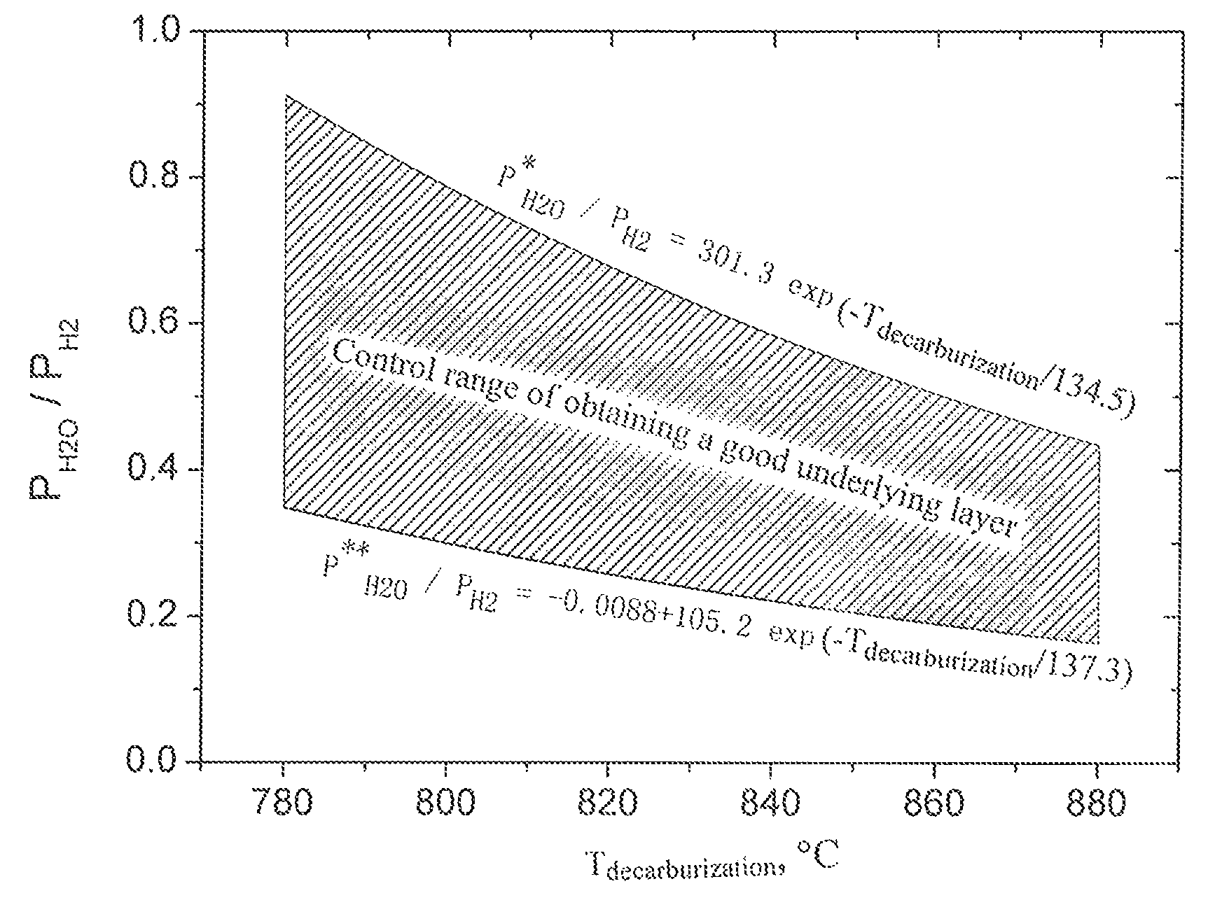
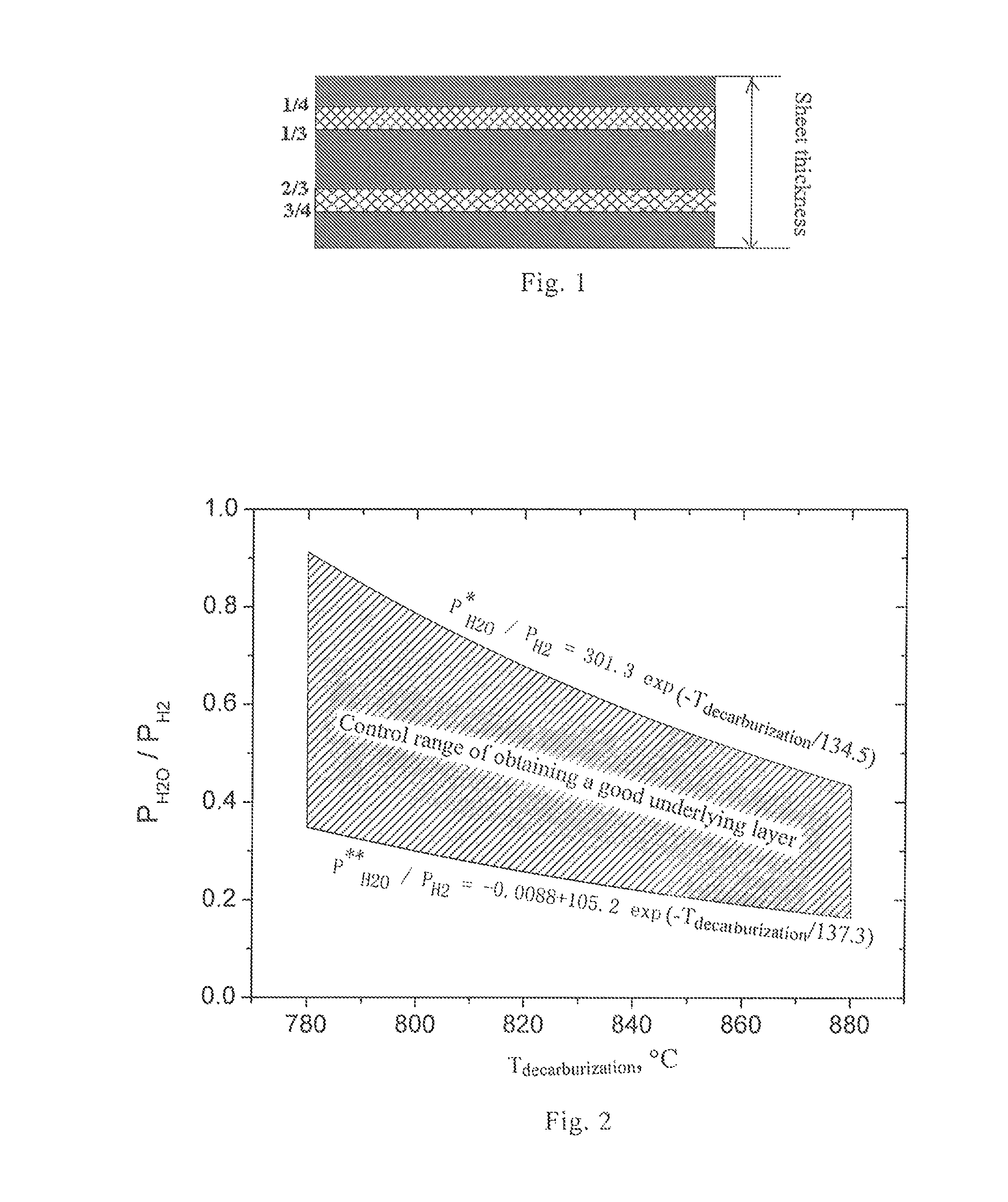
[0078]Composition A in Table 2 and hot rolling condition C in Table 3 were combined to carry out normalization experiments. The effect of normalization process condition 1120° C.×5 s+910° C.×70 s+20° C. / s, decarburizing time, temperature and dew point on magnetism and the underlying layer is shown in Table 7 and 8.

[0079]

TABLE 7Relationship between decarburizing temperature, time, dew pointand magnetismDecar-Proportion Decar-burizingDewof N2 inburizingTempera-PointProtectiveP17 / 50DescriptionTime (s)ture ° C.° C.AtmosphereB8 (T)(W / kg)Comparative 200770+1810%1.71 1.88ExampleInventive200790+4055%1.84 1.34ExampleInventive150830+7018%1.89 1.10ExampleInventive250850+6050%1.87 1.18ExampleInventive345850+5025%1.86 1.21ExampleInventive90870+7780%1.85 1.23ExampleComparative370890+8514%1.63 2.05ExampleComparative 150900+1988%1.51 2.41Example

[0080]

TABLE 8Relationship between decarburizing temperature, time, dew pointand the underlying layerDecar-Proportion NitrogenDecar-burizingDewof N2 inIncre-...


PUM

PropertyMeasurementUnit
temperatureaaaaaaaaaa

Abstract

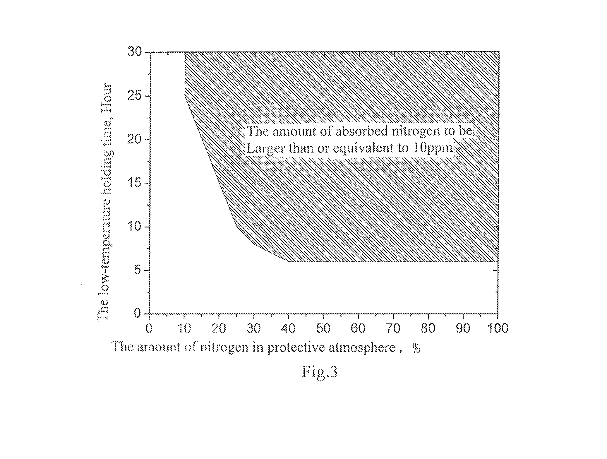
The invention provides a method for producing grain-oriented silicon steel with single cold rolling, comprising: 1) smelting, refining and continuous casting to obtain a casting blank; 2) hot rolling; 3) normalization, i.e. normalizing annealing and cooling; 4) cold-rolling, i.e. single cold rolling at a cold rolling reduction rate of 75-92%; 5) decarburizing annealing at 780-880° C. for 80-350 s in a protective atmosphere having a due point of 40-80° C., wherein the total oxygen [O] in the surface of the decarburized sheet: 171 / t≦[O]≦313 / t (t represents the actual thickness of the steel sheet in mm), the amount of absorbed nitrogen: 2-10 ppm; 6) high temperature annealing, wherein the dew point of the protective atmosphere: 0-50° C., the temperature holding time at the first stage: 6-30 h, the amount of absorbed nitrogen during high-temperature annealing: 10-40 ppm; 7) hot-leveling annealing. The invention may control the primary recrystallization microstructure of steel sheet effectively by controlling the normalization process of hot rolled sheet to form sufficient favorable (Al, Si)N inclusions from nitrogen absorbed by slab during decarburizing annealing and low-temperature holding of high-temperature annealing, facilitating the generation of stable, perfect secondary recrystallization microstructure of the final products. In addition, the invention avoids the impact of nitridation using ammonia on the underlying layer in prior art, and thus the formation of a good glass film underlying layer is favored.

Description

TECHNICAL FIELD[0001]The invention relates to a method for manufacturing grain-oriented silicon steel, particularly to a method for manufacturing grain-oriented silicon steel with single cold rolling.BACKGROUND ART[0002]Conventionally, grain-oriented silicon steel is manufactured by the following process, wherein:[0003]Steel is secondarily refined and alloyed in a converter (or an electric furnace), and then continuously cast into slab, the basic chemical composition of which includes Si (2.5-4.5%), C (0.01-0.10%), Mn (0.03-0.1%), S (0.012-0.050%), Als (0.01-0.05%) and N (0.003-0.012%), in some instances further comprising one or more elements of Cu, Mo, Sb, Cr, B, Bi and the like, balanced by iron and some unavailable inclusions;[0004]The slab is heated to about 1400° C. in a special-purpose high-temperature heater and kept at this temperature for more than 30 minutes to sufficiently solid dissolve favorable inclusions, so that dispersed fine particles of secondary phase, namely in...

Claims


Application Information

Patent Timeline
Patent Type & Authority Patents(United States)
IPC IPC(8): B21B27/06C21D8/12B21B1/36B21B3/00B21B9/00C21D1/28C21D9/46C22C38/00C22C38/02C22C38/04C22C38/06C22C38/16H01F1/147
CPCC21D8/12C21D8/1255C21D8/1272C21D9/46C22C38/001C22C38/008C22C38/02C22C38/04C22C38/06C22C38/16H01F1/14775B21B1/36B21B3/00B21B9/00C21D1/28C21D8/1233C21D8/1283
Inventor LI, GUOBAOZHANG, PIJUNYANG, YONGJIESHEN, KANYIHU, ZHUOCHAOWU, PEIWENJIN, WEIZHONGJIANG, QUANLI
Owner BAOSHAN IRON & STEEL CO LTD
Learn More