
System and method for producing LNG from contaminated gas streams

a gas stream and gas technology, applied in the direction of refrigeration machines, lighting and heating apparatus, solidification, etc., can solve the problems of affecting the safety of workers, and containing more than about 5 percent methane (preferably not more than about 2 percent), so as to reduce the requirement of horsepower and compressors, eliminate or significantly reduce any adverse environmental impa

Active Publication Date: 2015-04-28
BCCK HLDG CO
View PDF6 Cites 20 Cited by
  • Summary
  • Abstract
  • Description
  • Claims
  • Application Information

AI Technical Summary

Benefits of technology

This patent is about a new technology that can process and liquefy methane at low temperatures without needing a large external refrigeration system. This means that less energy and equipment is needed, which saves money and reduces environmental impact. The technology can be used in small facilities and can even be provided to locations where methane would normally be wasted.

Problems solved by technology

Naturally occurring methane is often encountered in coal mines, where it poses a significant risk to miners and to the mine subsurface equipment and inventory.
This risk arises from miners being unable to breathe methane gas and also because air containing more than about 5 percent methane (preferably not more than about 2 percent) poses a significant risk of explosion.
Once the mining equipment reaches the vertical shafts drilled to recover methane from the formation, collapses can occur that produce another kind of methane-containing gas referred to as “gob gas,” which is also extremely hazardous.
For this reason, even where the flash gas is captured without exposing it to air, the methane in the flash gas cannot readily be re-liquefied without first removing the nitrogen.
Although the amount of methane in the flash gas is relatively minor compared to the total amount being loaded, it may not enough to justify economically the investment and expense required to remove the nitrogen and then re-liquefy the methane using conventional technology.
Unfortunately, this can cause operators to resort to the more expedient but less environmentally responsible alternatives of venting or flaring the flash gas.

Method used


Image

  • System and method for producing LNG from contaminated gas streams
  • System and method for producing LNG from contaminated gas streams
  • System and method for producing LNG from contaminated gas streams

Examples


Embodiment Construction

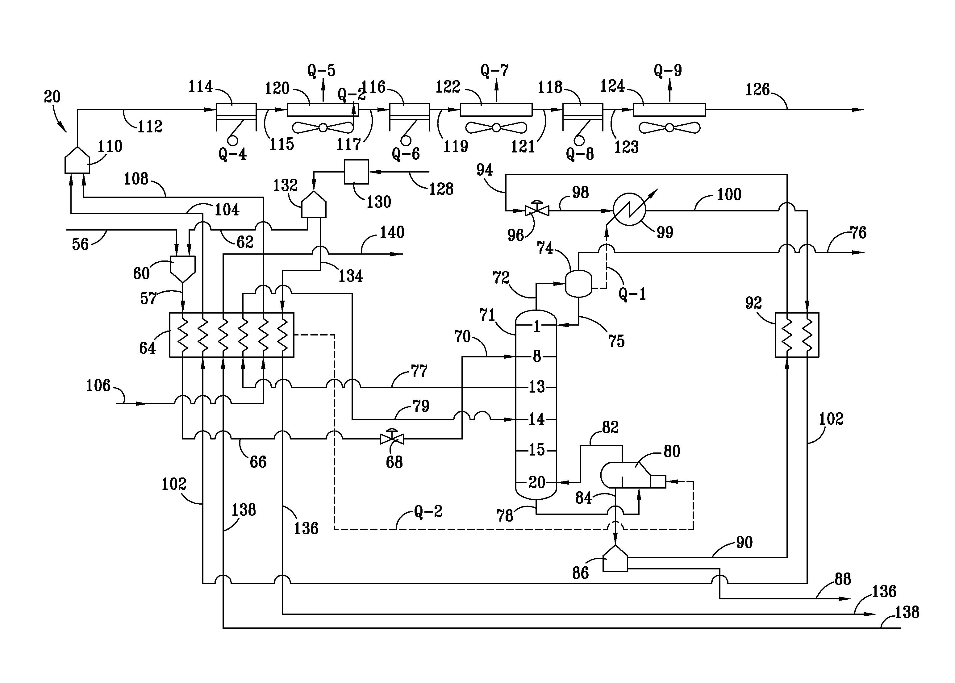
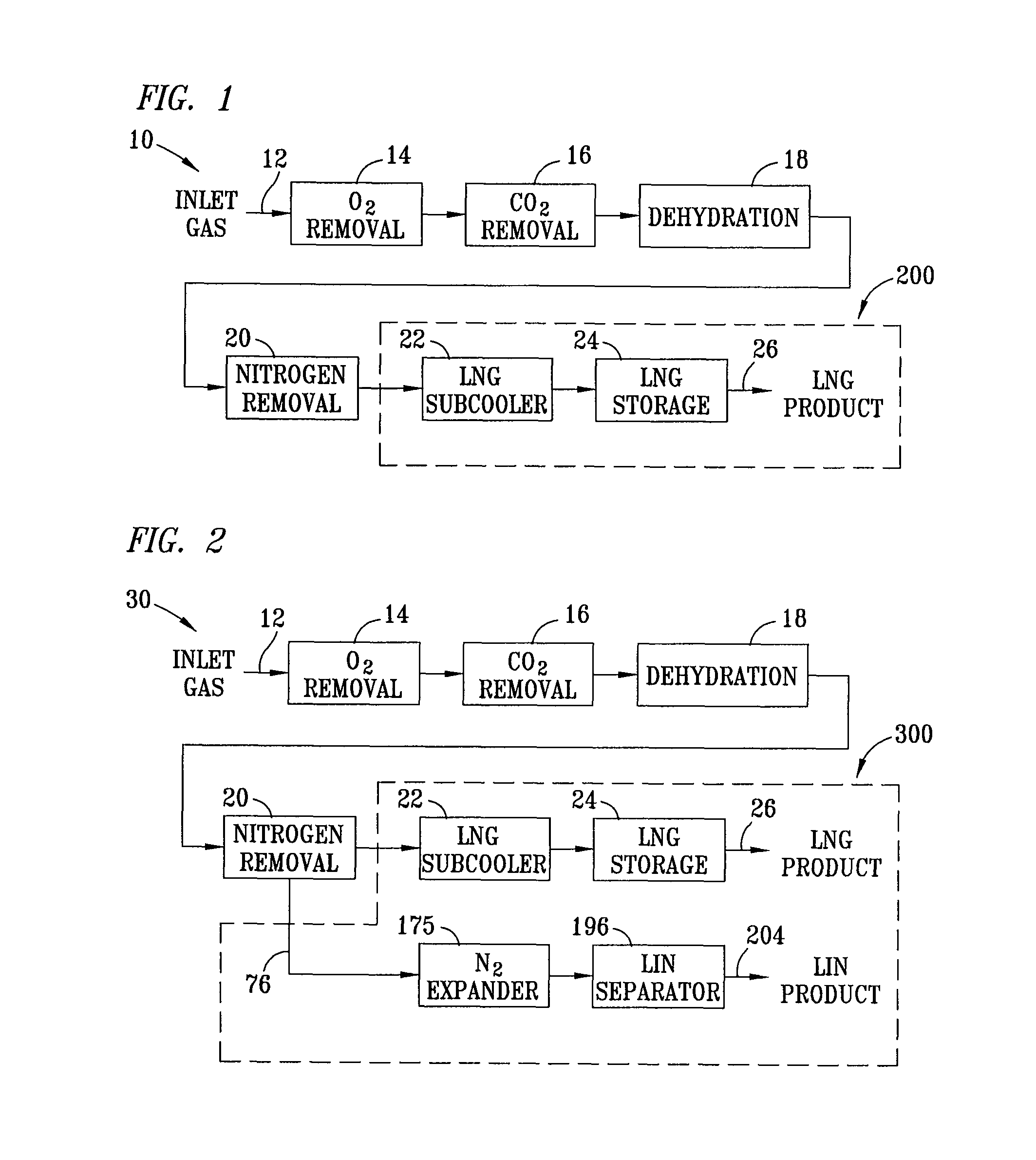
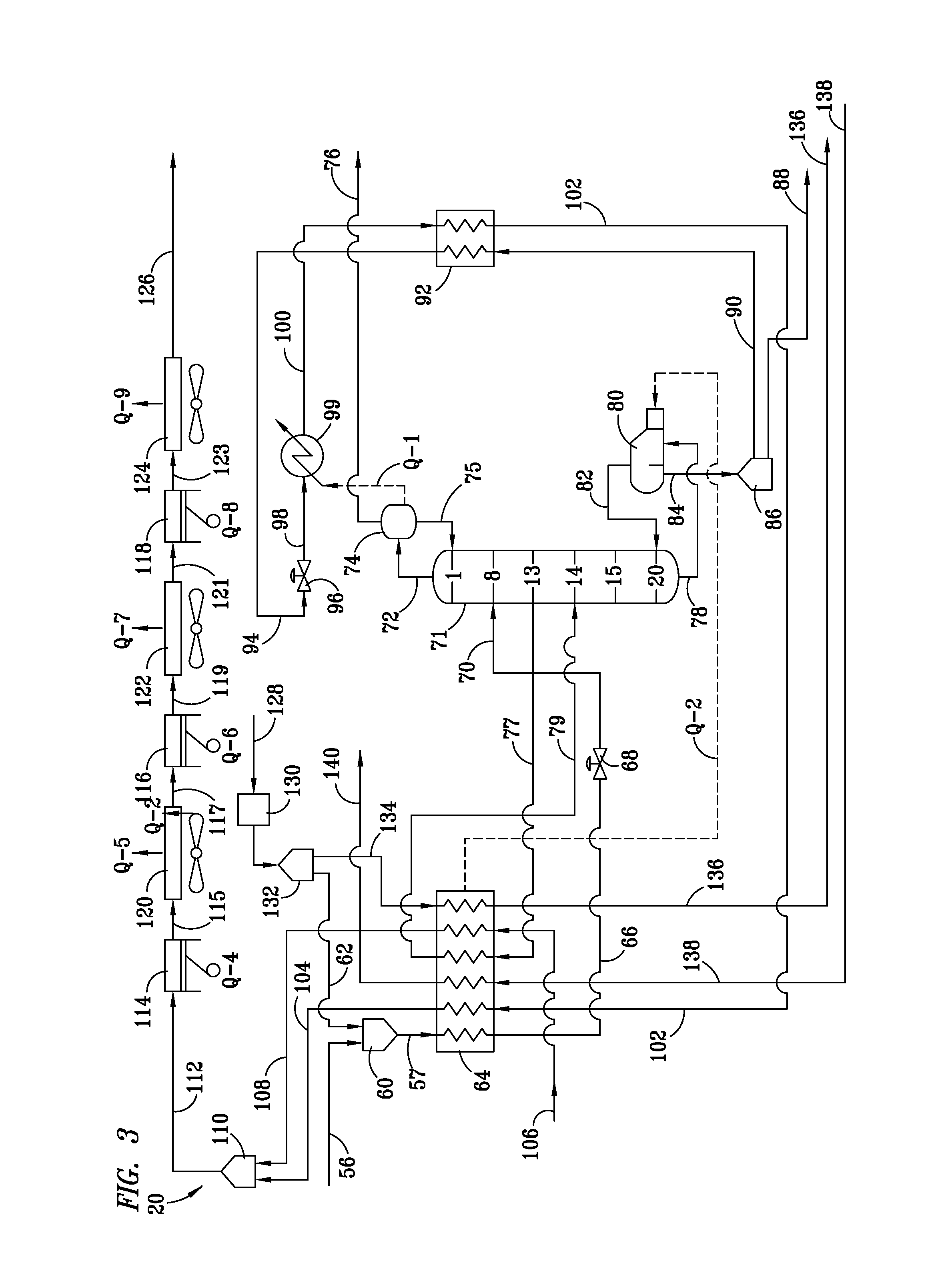
[0027]Referring to FIG. 1, one satisfactory system 10 of the invention comprises processing equipment useful for receiving methane gas and cooling it to form LNG without the use of external refrigeration or a recirculated refrigerant. Although the source of the methane gas is not critical to the system and method of the invention, some suitable sources of methane gas for use in the invention are coal mines, LNG loading facilities, and other industrial or geologic sources. The methane used as inlet gas stream 12 will typically contain other gases as well, with nitrogen, oxygen, carbon dioxide and water vapor being the most notable examples. Where present, it is generally preferable for purposes of the present invention to remove as much of the oxygen, carbon dioxide and water vapor as is reasonably possible prior to implementing the nitrogen removal and methane liquefaction portions of the invention. For this reason, system 10 of the invention as depicted in FIG. 1 includes first, se...


PUM


Abstract

A system and method for removing nitrogen and producing liquefied natural gas (“LNG”) from methane without the need for external refrigeration. The invention also relates to a system and method for removing nitrogen from methane and for producing liquefied nitrogen in addition to LNG. The system and method of the invention are particularly suitable for use in recovering and processing comparatively small volumes of methane from coal mines or from flash gas captured at an LNG loading site.

Description

CROSS-REFERENCE TO RELATED APPLICATION[0001]This application claims the benefit of U.S. Provisional Application No. 61 / 256,053, filed Oct. 29, 2009.BACKGROUND OF THE INVENTION[0002]1. Field of the Invention[0003]This invention relates to a system and method for removing nitrogen and producing liquefied natural gas (“LNG”) from gaseous streams containing methane and other impurities without the need for an external refrigeration system. The invention also relates to a system and method for removing nitrogen from methane and for producing liquefied nitrogen in addition to LNG. The system and method of the invention are particularly suitable for use in recovering and processing comparatively small volumes of methane from coal mine vent streams or streams containing methane and nitrogen captured as flash gas at an LNG loading site.[0004]2. Description of Related Art[0005]Because many sources of methane produced during mining, energy transport or other industrial applications are not loc...

Claims


Application Information

Patent Timeline
Patent Type & Authority Patents(United States)
IPC IPC(8): F25J3/00F25J3/02
CPCF25J3/0209F25J3/0233F25J3/0257F25J2210/60F25J2200/02F25J2200/50F25J2200/74F25J2210/40F25J2215/04F25J2220/62F25J2230/20F25J2240/02F25J2240/12F25J2245/90F25J2270/02F25J2270/04F25J2270/06F25J2270/88F25J2290/34F25J2290/62Y10S62/927
Inventor BUTTS, RAYBURN C.
Owner BCCK HLDG CO
Learn More