
TMR/CPP reader for narrow reader gap application

a reader gap and reader technology, applied in the field of magnetic read heads, can solve the problems of limited amount by which the thickness of the reader gap can be decreased, the limitations of current available manufacturing methods, and the inability of the reader gap of the conventional tmr/cpp read head to meet the requirements of future high density media

Active Publication Date: 2015-04-07
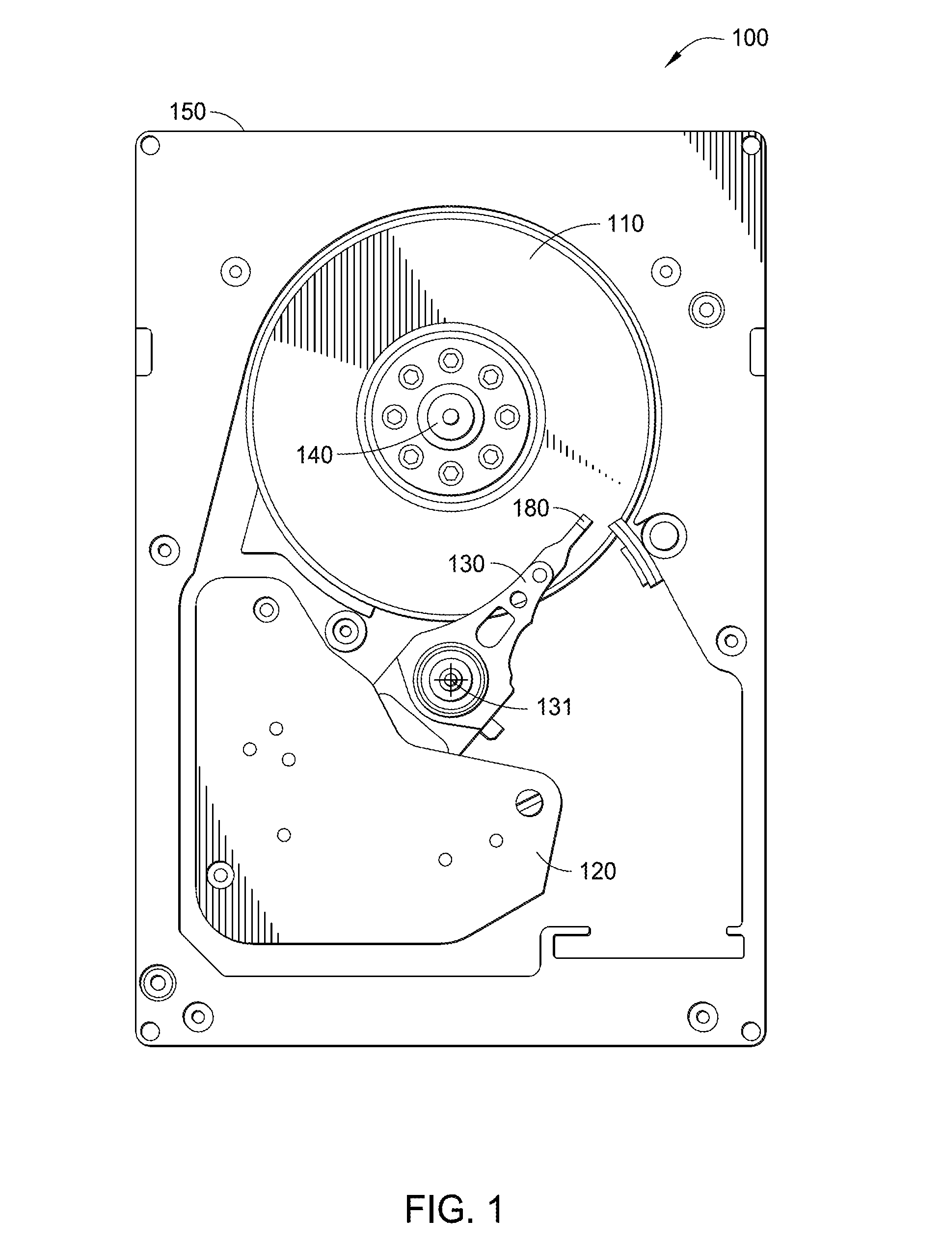
WESTERN DIGITAL TECH INC
View PDF28 Cites 17 Cited by
  • Summary
  • Abstract
  • Description
  • Claims
  • Application Information

AI Technical Summary

Benefits of technology

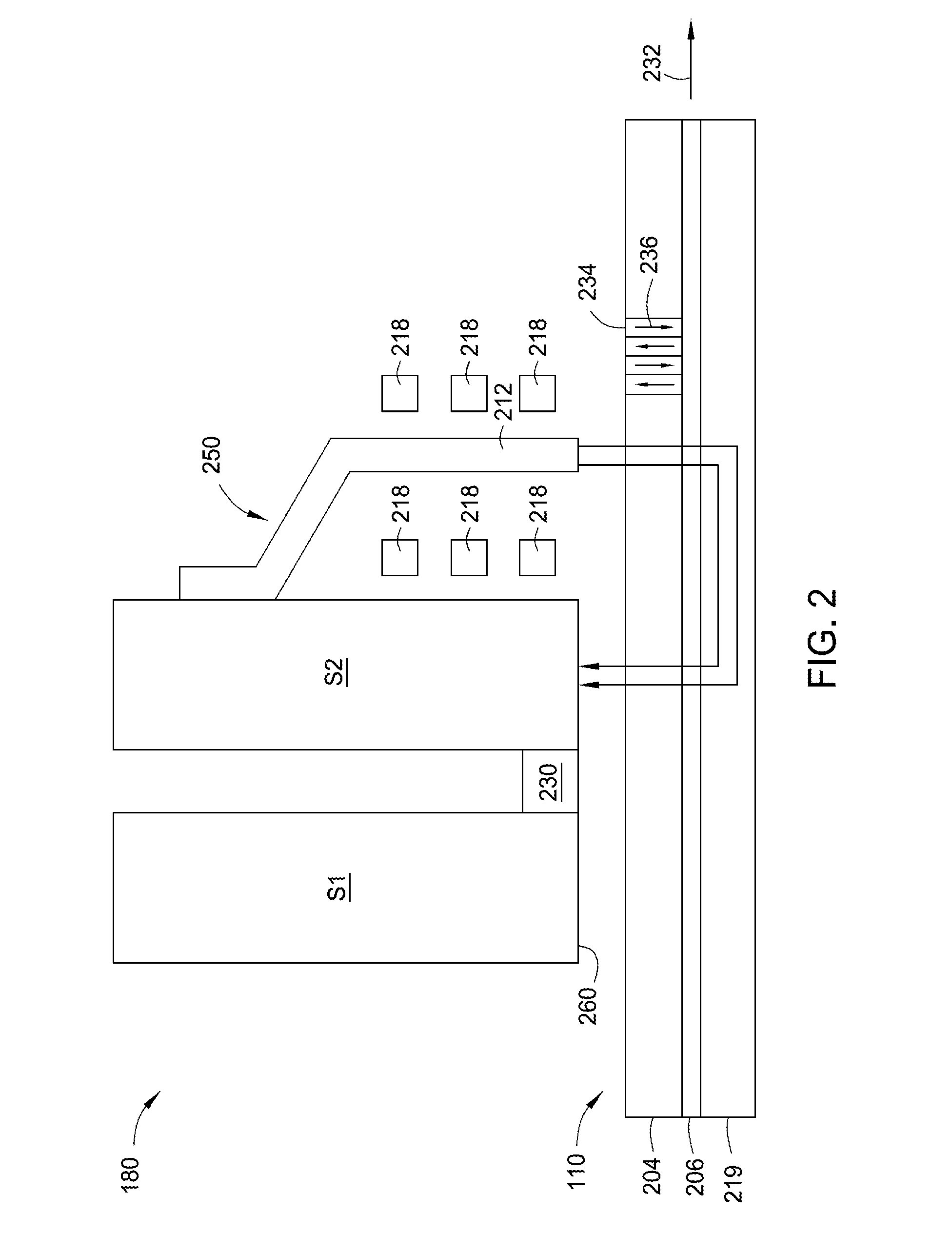
The embodiments of this patent are about a sensor structure and a magnetic read head. The sensor structure has a pinned magnetic structure and a reader gap structure. The reader gap structure has a spacer layer and a first part of free layer recessed from the media facing surface and partially overlapping the pinned magnetic structure. A second part of free layer extends to the media facing surface and overlaps the first part of free layer. The cap layer extends to the media facing surface and overlaps the second part of free layer. The angle of the common face of the layers is on an angle relative to the media facing surface. This structure allows for more efficient sensor performance and improved magnetic read head performance.

Problems solved by technology

However, the amount by which the reader gap thickness can be decreased has been limited by physical limitations of sensors and also by the limitations of currently available manufacturing methods.
The reader gaps for conventional TMR / CPP read heads cannot meet the requirements for future high density media simply by thinning the functional layers of the read head.
However, aside from fabrication challenges, the reduction in the pinning energy and the stability of the pinned layer at the MFS has been problematic for read heads using the recessed pinned layers.
However, a great challenge related to yield and the sensor stability still remains.

Method used


Image

  • TMR/CPP reader for narrow reader gap application
  • TMR/CPP reader for narrow reader gap application
  • TMR/CPP reader for narrow reader gap application

Examples


Embodiment Construction

[0019]In the following, reference is made to embodiments of the invention. However, it should be understood that the invention is not limited to specific described embodiments. Instead, any combination of the following features and elements, whether related to different embodiments or not, is contemplated to implement and practice the invention. Furthermore, although embodiments of the invention may achieve advantages over other possible solutions and / or over the prior art, whether or not a particular advantage is achieved by a given embodiment is not limiting of the invention. Thus, the following aspects, features, embodiments and advantages are merely illustrative and are not considered elements or limitations of the appended claims except where explicitly recited in a claim(s). Likewise, reference to “the invention” shall not be construed as a generalization of any inventive subject matter disclosed herein and shall not be considered to be an element or limitation of the appended...


PUM

PropertyMeasurementUnit
negative angleaaaaaaaaaa
angleaaaaaaaaaa
widthaaaaaaaaaa

Abstract

The embodiments disclosed generally relate to a read head in a magnetic recording head. The read head utilizes a sensor structure having: a pinned magnetic structure recessed from a media facing surface; and a reader gap structure. The reader gap structure has a spacer layer recessed from the media facing surface and disposed on top of the pinned magnetic structure, a recessed first free layer partially recessed from the media facing surface and disposed on top of the barrier layer, a second free layer extending to the media facing surface an disposed on top of the barrier layer, and a cap layer extending to the media facing surface disposed atop the second free layer. The pinned magnetic structure, the spacer, and the first free layer have a common face which is on an angle relative to the media facing surface.

Description

BACKGROUND OF THE INVENTION[0001]1. Field of the Invention[0002]Embodiments disclosed herein generally relate to a magnetic read head for use in a hard disk drive.[0003]2. Description of the Related Art[0004]At the heart of a computer is a magnetic hard disk drive (HDD) which typically includes a rotating magnetic disk, a slider that has read and write heads, a suspension arm above the rotating disk and an actuator arm that swings the suspension arm to place the read and / or write heads over selected circular tracks on the rotating disk. The suspension arm biases the slider towards the surface of the disk when the disk is not rotating but, when the disk rotates, air is swirled by the rotating disk adjacent to a media facing surface (MFS), such as an air bearing surface (ABS) of the slider causing the slider to ride on an air bearing a slight distance from the surface of the rotating disk. When the slider rides on the air bearing, the write and read heads are employed for writing magn...

Claims


Application Information

Patent Timeline
Patent Type & Authority Patents(United States)
IPC IPC(8): G11B5/127G11B5/39
CPCG11B5/3945G01R33/093G01R33/098G11B5/3909G11B5/3912G11B5/3954G11B5/398G11B5/1272G11B5/1475
Inventor GAO, ZHENGFREITAG, JAMES MACHO, KUOK SANTSANG, CHING HWAJU, KOCHAN
Owner WESTERN DIGITAL TECH INC
Learn More