Method for carburizing tantalum member, and tantalum member

a technology of tantalum and carburizing parts, which is applied in the field of carburizing tantalum members and tantalum members, can solve the problems of no specific method for carburizing tantalum containers and tantalum lids, and have been discussed in the literature. , to achieve the effect of reducing distortion of openings, good flatness of planar parts, and uniform manner

Active Publication Date: 2015-03-24
TOYO TANSO KK
View PDF14 Cites 2 Cited by
  • Summary
  • Abstract
  • Description
  • Claims
  • Application Information

AI Technical Summary

Benefits of technology

[0035]In the first aspect of the present invention, a tantalum member is less deformed by carburization and can be carburized with good flatness of the planar part and in a uniform manner.
[0036]In the second aspect of the present invention, in carburizing a tantalum container with an opening, the opening can be prevented from being enlarged by the carburization and the distortion of the opening can be reduced. Therefore, the hermeticity of the tantalum container when fitted with a lid can be increased.

Problems solved by technology

However, no specific method for carburizing a tantalum container and a tantalum lid has been discussed in the literatures.

Method used


Image

  • Method for carburizing tantalum member, and tantalum member
  • Method for carburizing tantalum member, and tantalum member
  • Method for carburizing tantalum member, and tantalum member

Examples


example 1

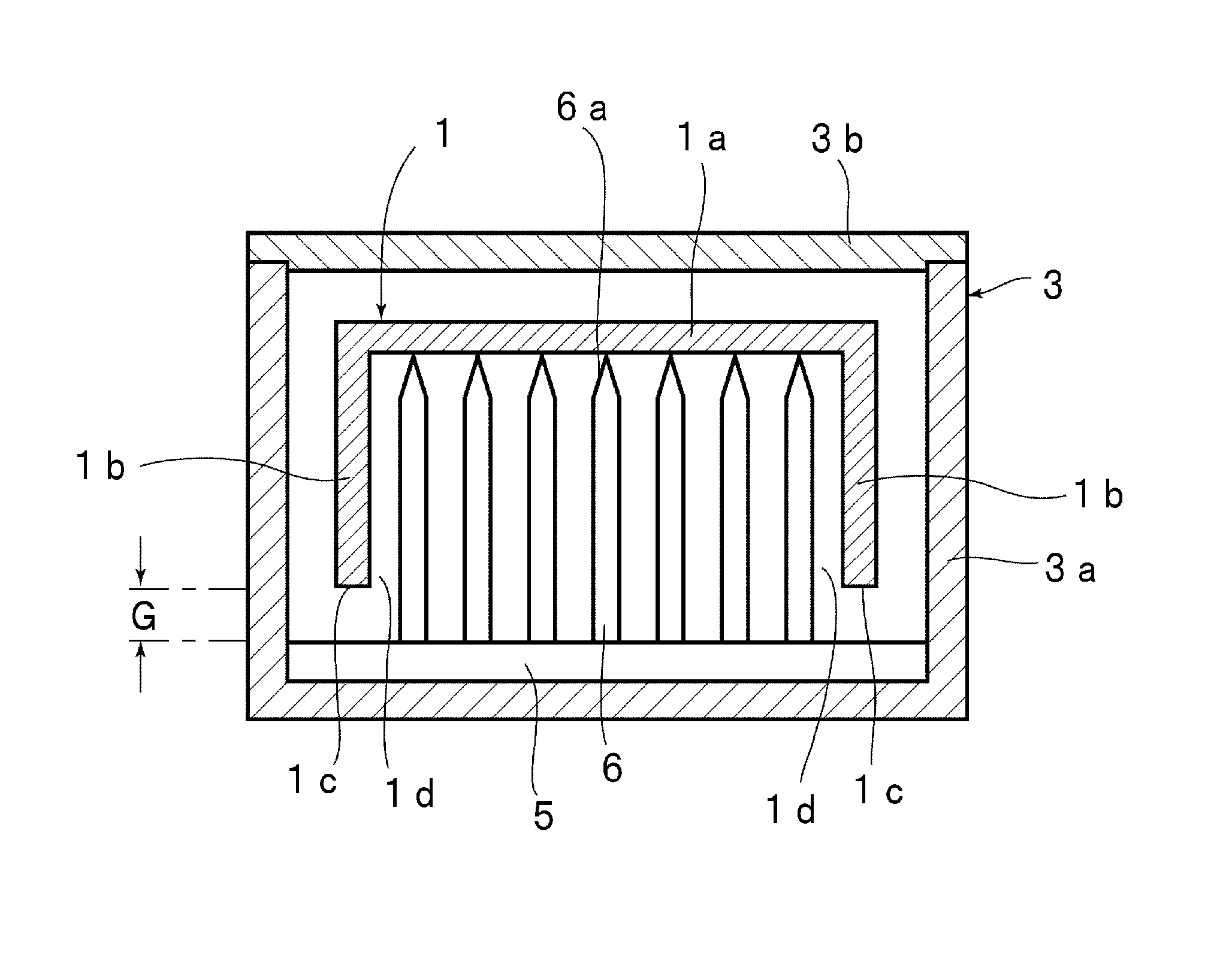
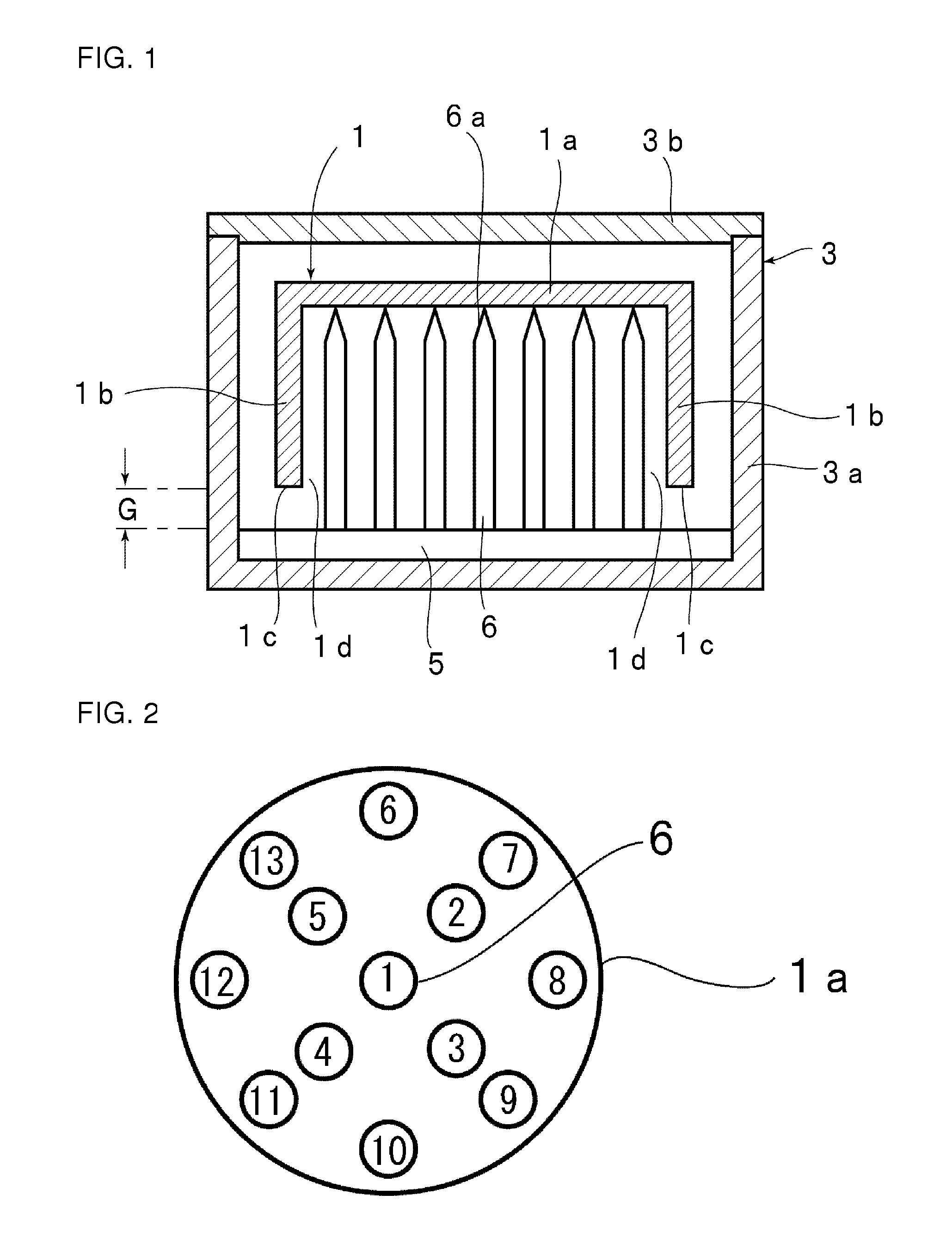
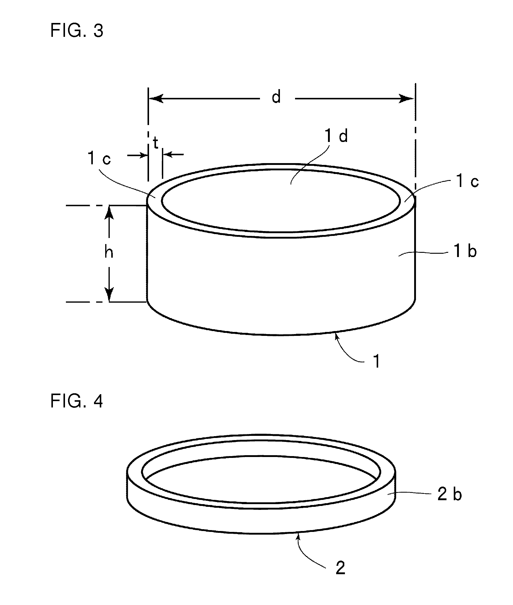
[0096]A tantalum container 1 was carburized using a chamber 3 shown in FIG. 1. The tantalum container 1 used was one shown in FIG. 3 and having an outside diameter d of 158 mm, a height h of 60 mm, and a thickness t of 3 mm. Therefore, the inside diameter of the planar part 1a on the inside of the tantalum container 1 is 152 mm and the area thereof is 18136 mm2.

[0097]In this example, as shown in FIG. 2, thirteen support rods 6 were arranged with respect to the planar part 1a. Therefore, the planar part 1a was supported by the support rods 6, one per 1395 mm2 of the area of the planar part 1.

[0098]The chamber 3 used was a chamber 3 whose interior is a columnar space measuring 210 mm in diameter and 90 mm high. The material used for the chamber container 3a and the chamber lid 3b was an isotropic graphite material with a bulk density of 1.8.

[0099]The support rods 6 used were those measuring 6 mm in diameter and 75 mm long. The length of the tapered portion of the distal end 6a was 15 ...

example 2

[0108]A tantalum container 1 was carburized in the same manner as in Example 1 except that four support rods 6 were distributed with respect to the planar part 1a of the tantalum container 1 as shown in FIG. 8.

[0109]The planar part 1a of the tantalum container 1 before and after the carburization process was determined in terms of out-of-roundness and out-of-flatness in the same manner as described above, and the determination results are shown in Table 1.

example 3

[0110]A tantalum container 1 was carburized in the same manner as in Example 1 except that seventeen support rods 6 were distributed with respect to the planar part 1a of the tantalum container 1 as shown in FIG. 9.

[0111]The planar part 1a of the tantalum container 1 before and after the carburization process was determined in terms of out-of-roundness and out-of-flatness in the same manner as described above, and the determination results are shown in Table 1.


PUM

PropertyMeasurementUnit
areaaaaaaaaaaa
diameteraaaaaaaaaa
sizeaaaaaaaaaa

Abstract

Provided is a method for carburizing a tantalum member whereby the tantalum member is less deformed by carburization and can be carburized with good flatness of the planar part thereof and in a uniform manner. The method is a method for subjecting a tantalum member 1 made of tantalum or a tantalum alloy and having a planar part 1a to a carburization process for allowing carbon to penetrate the member 1 from the surface toward the inner portion thereof and includes the steps of: setting the tantalum member 1 in a chamber 3 containing a carbon source by supporting the planar part 1a on a plurality of support rods 6 tapered at distal ends 6a thereof; and subjecting the tantalum member 1 to a carburization process by reducing in pressure and heating the interior of the chamber 3 to allow carbon derived from the carbon source to penetrate the tantalum member 1 from the surface thereof.

Description

TECHNICAL FIELD[0001]This invention relates to methods for subjecting a member made of tantalum or a tantalum alloy, such as a tantalum container or a tantalum lid, to a carburization process for allowing carbon to penetrate the member from its surface toward its inner portion, and to tantalum members obtained by the methods.BACKGROUND ART[0002]Silicon carbide (SiC) is considered as capable of achieving high-temperature performance, high-frequency performance, voltage resistance, and environment resistance each of which could not be achieved by conventional semiconductor materials, such as silicon (Si) and barium arsenide (BaAs), and is therefore expected as a semiconductor material for next-generation power devices and high-frequency devices.[0003]Patent Literature 1 proposes to use a tantalum container having a tantalum carbide layer formed on the surface thereof as a chamber in thermally annealing the surface of a single crystal silicon carbide substrate and in growing a single c...

Claims


Application Information

Patent Timeline
Patent Type & Authority Patents(United States)
IPC IPC(8): C23C8/22C21D9/00C23C8/64
CPCC23C8/64
Inventor ABE, YOSHIHISAWATANABE, MASANARITAMURA, OSAMU
Owner TOYO TANSO KK
Why Eureka
Try Eureka