Liquid ejecting head and liquid ejecting apparatus
a liquid ejecting head and liquid ejecting technology, which is applied in the direction of instruments, inks, measurement apparatus components, etc., can solve the problems of unstable ejecting of inks, and achieve the effect of suppressing unstable ejecting and improving the reliability of the liquid ejecting apparatus
- Summary
- Abstract
- Description
- Claims
- Application Information
AI Technical Summary
Benefits of technology
Problems solved by technology
Method used
Image

Examples
Embodiment Construction
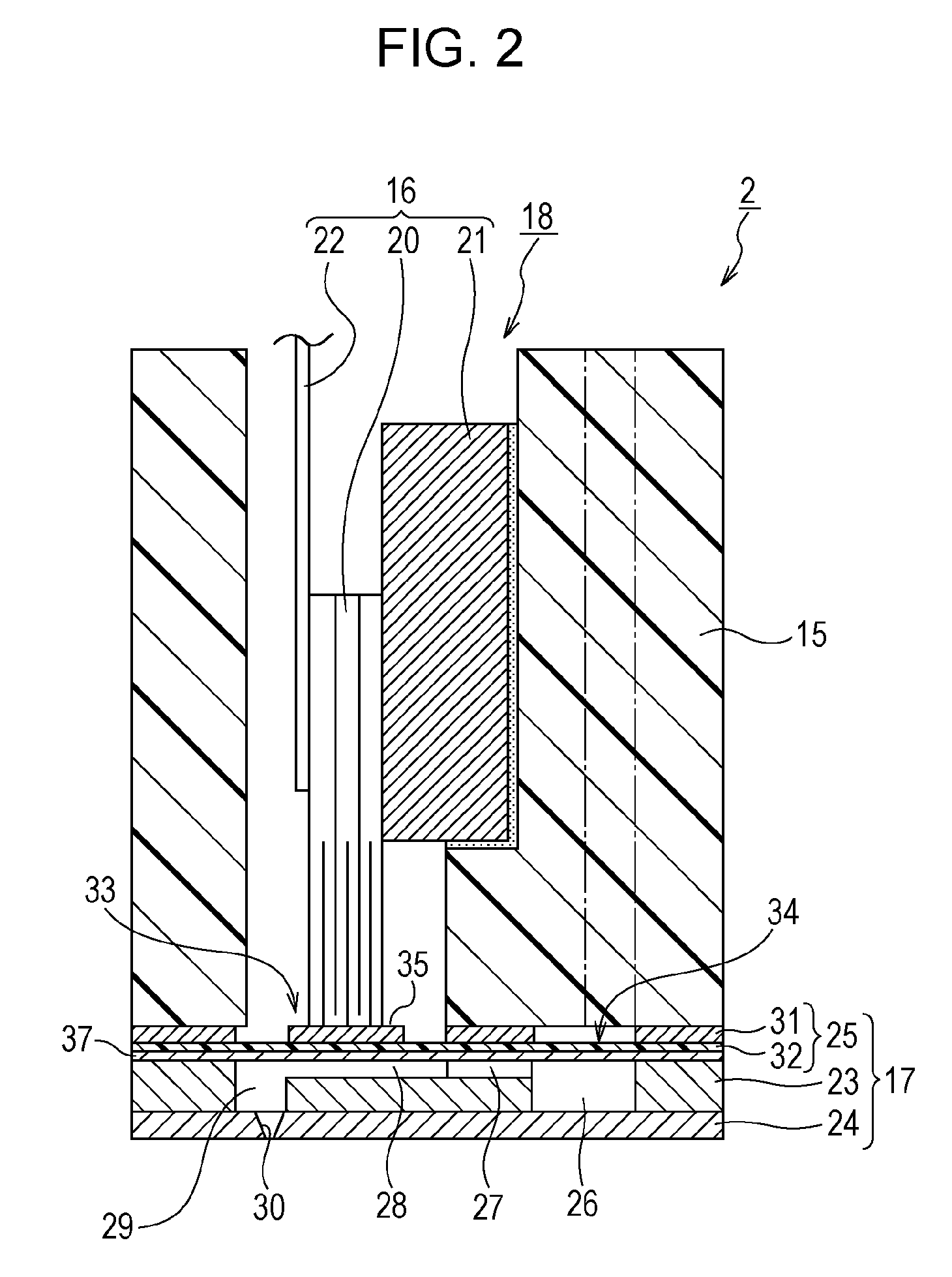
[0025]Hereinafter, a mode for carrying out the invention is described with reference to the accompanying drawings. In an embodiment which will be described below, various limitations are made as a preferable specific example of the invention. However, the scope of the invention is not limited to the embodiment unless description limiting the invention is particularly made in the following explanation. Further, a liquid ejecting head according to the invention is explained by taking a recording head 2 as one type of the liquid ejecting head, hereinafter.
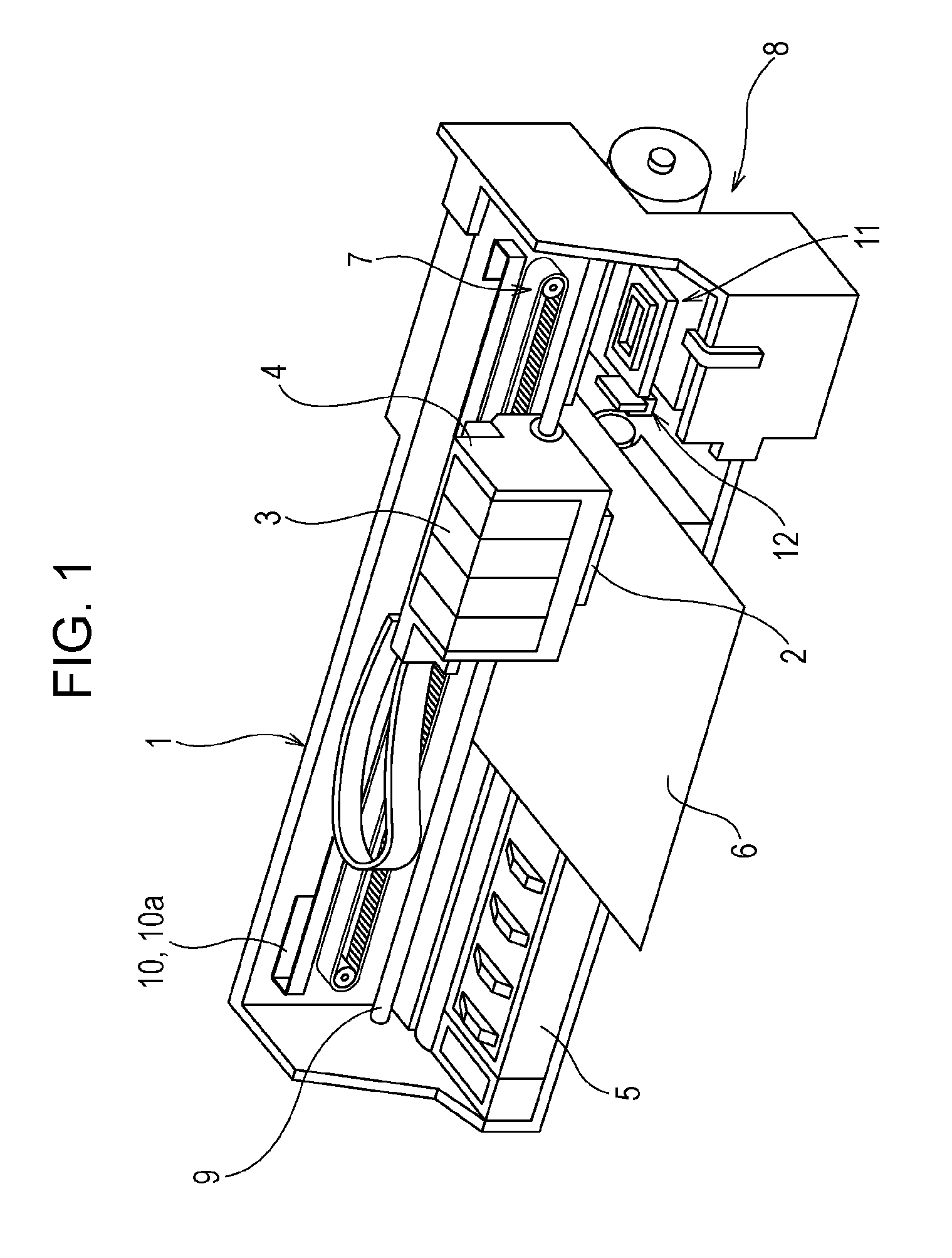
[0026]FIG. 1 is a perspective view illustrating a configuration of a printer 1. The printer 1 includes a carriage 4, a platen 5, a carriage movement mechanism 7, and a transportation mechanism 8. The recording head 2 as one type of the liquid ejecting head is attached to the carriage 4. An ink cartridge 3 as one type of a liquid supply source is attached to the carriage 4 in a detachable manner. The platen 5 is arranged at the lower s...
PUM
| Property | Measurement | Unit |
|---|---|---|
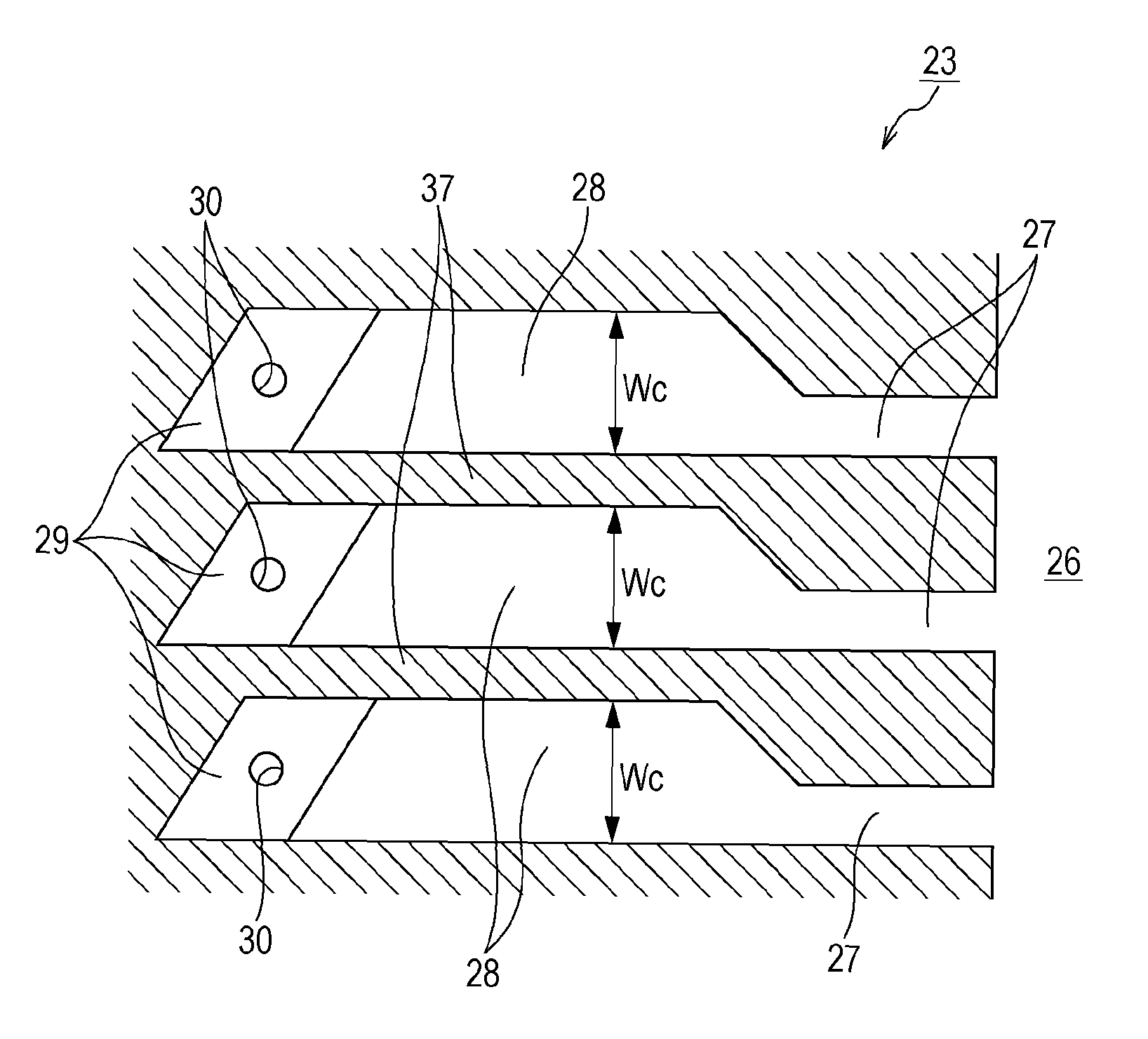
| width Wc | aaaaa | aaaaa |
| particle diameter | aaaaa | aaaaa |
| widths Wc | aaaaa | aaaaa |
Abstract
Description
Claims
Application Information
 - R&D
- Intellectual Property
- Life Sciences
- Materials
- Tech Scout
- Unparalleled Data Quality
- Higher Quality Content
- 60% Fewer Hallucinations
Browse by: Latest US Patents, China's latest patents, Technical Efficacy Thesaurus, Application Domain, Technology Topic, Popular Technical Reports.
© 2025 PatSnap. All rights reserved.Legal|Privacy policy|Modern Slavery Act Transparency Statement|Sitemap|About US| Contact US: help@patsnap.com