
Automated set-up for cell sorting

a cell sorting and automatic technology, applied in non-electric variable control, process and machine control, instruments, etc., can solve the problem that the method requires a substantial amount of user input at the time of set-up

Active Publication Date: 2015-03-10
BECTON DICKINSON & CO
View PDF32 Cites 141 Cited by
  • Summary
  • Abstract
  • Description
  • Claims
  • Application Information

AI Technical Summary

Benefits of technology

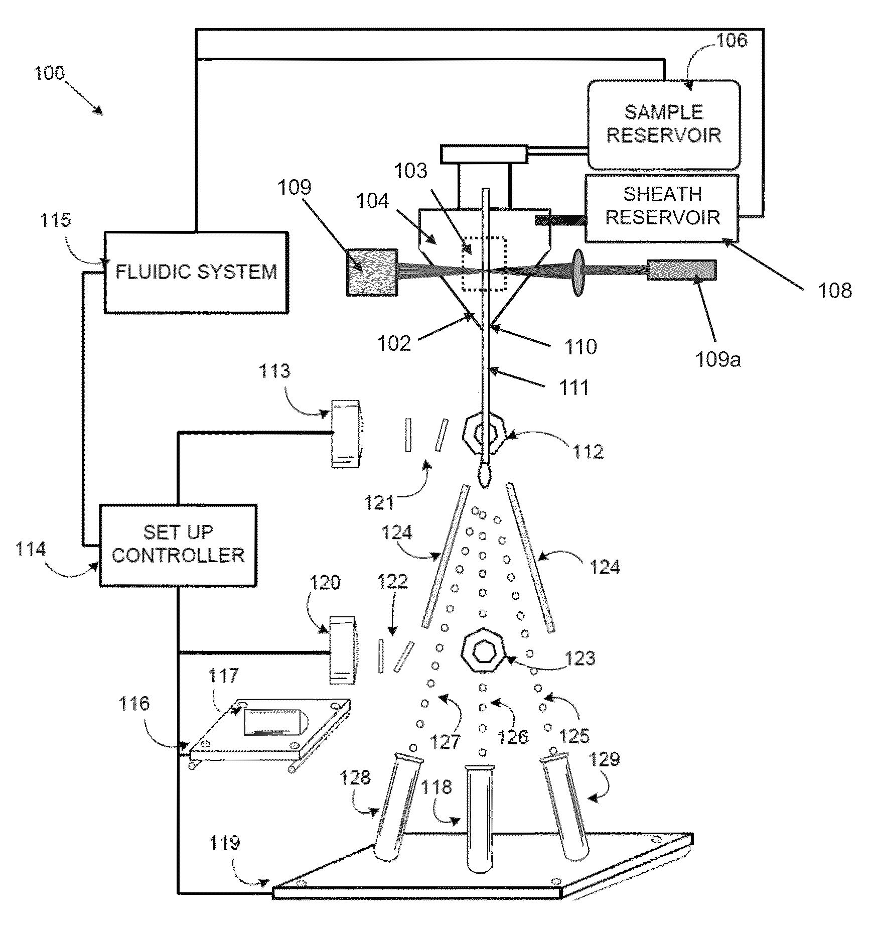
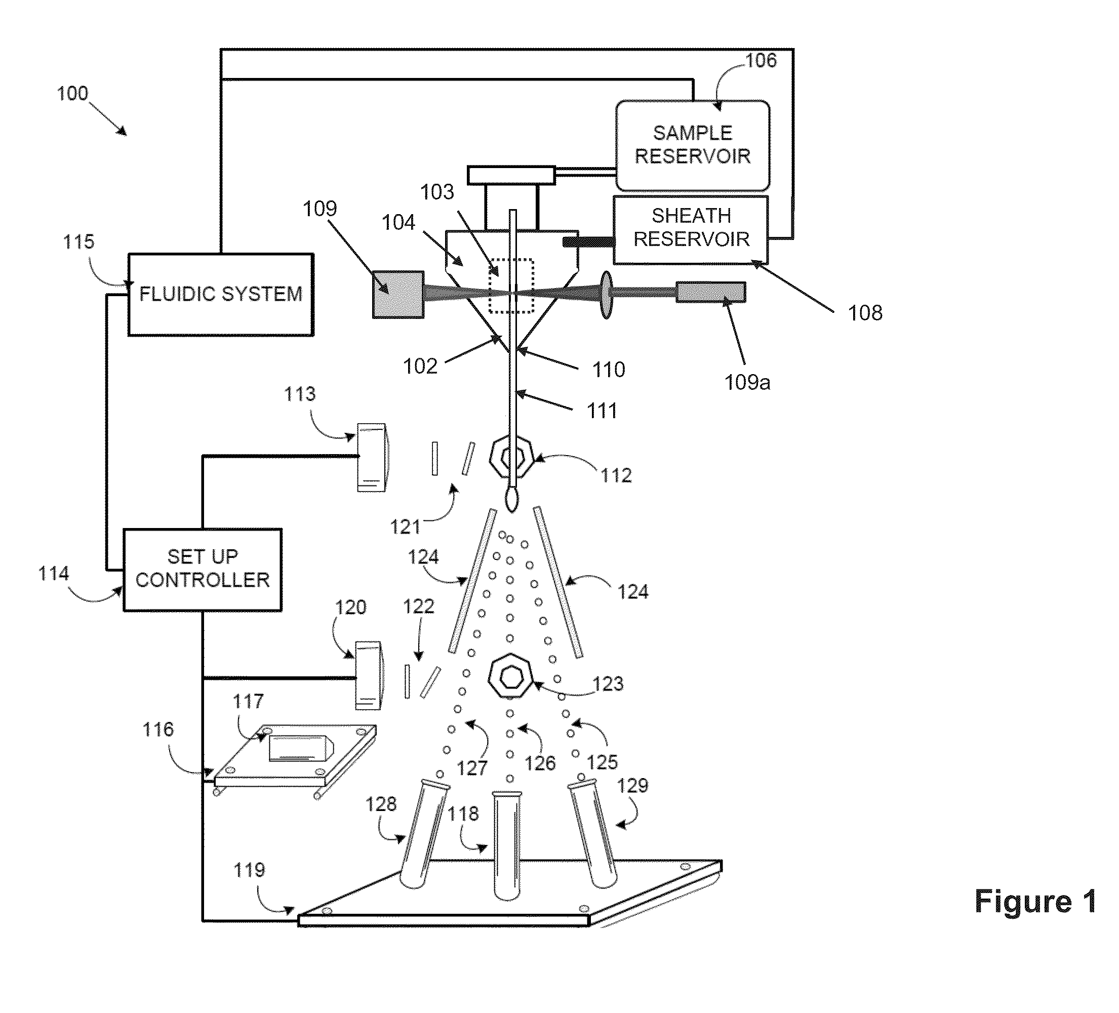
[0003]Within the flow cell, a liquid sheath is formed around the cell stream to impart a substantially uniform velocity on the cell stream. The flow cell hydrodynamically focuses the cells within the stream to pass through the center of a laser beam in a flow cell. The point at which the cells intersect the laser beam is commonly known as the interrogation point. As a cell moves through the interrogation point, it causes the laser light to scatter. The laser light also excites components in the cell stream that have fluorescent properties, such as fluorescent markers that have been added to the fluid sample and adhered to certain cells of interest, or fluorescent beads mixed into the stream. The flow cytometer includes an appropriate detection system consisting of photomultiplier tubes, photodiodes or other light detecting devices, which are focused at the intersection point. The flow cytometer analyzes the detected light to measure physical and fluorescent properties of the cell. The flow cytometer can further sort the cells based on these measured properties. The flow stream exits the flow cell via a nozzle with a nozzle diameter that is appropriate for the fluidics system and sort rate desired.
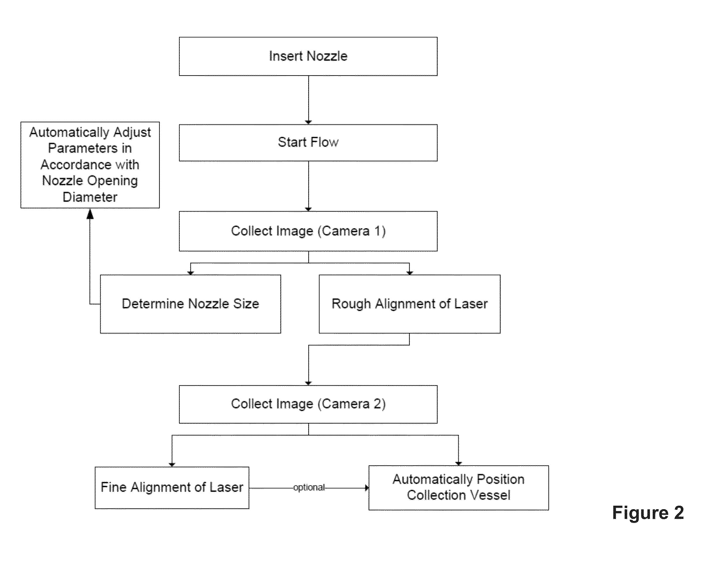
[0008]In certain embodiments, the subject systems are configured to reduce the need for user input or manual adjustment during sample analysis with a flow cytometer. In some embodiments, systems of interest may be partially or fully automated so that adjustments to parameters of a flow cytometer are processor controlled. In certain embodiments, the subject systems are configured to adjust one or more parameters of the flow cytometer without any human input.

Problems solved by technology

Although this method generally enables the flow cytometer to dispense sorted cells into collection vessels and therefore sort the cells of interest with reasonable accuracy, the method requires a substantial amount of user input at the time of set-up.

Method used


Image

  • Automated set-up for cell sorting
  • Automated set-up for cell sorting
  • Automated set-up for cell sorting

Examples


Embodiment Construction

[0019]Before the present invention is described in greater detail, it is to be understood that this invention is not limited to particular embodiments described, as such may vary. It is also to be understood that the terminology used herein is for the purpose of describing particular embodiments only, and is not intended to be limiting, since the scope of the present invention will be limited only by the appended claims.

[0020]Where a range of values is provided, it is understood that each intervening value, to the tenth of the unit of the lower limit unless the context clearly dictates otherwise, between the upper and lower limit of that range and any other stated or intervening value in that stated range, is encompassed within the invention. The upper and lower limits of these smaller ranges may independently be included in the smaller ranges and are also encompassed within the invention, subject to any specifically excluded limit in the stated range. Where the stated range include...


PUM

PropertyMeasurementUnit
angleaaaaaaaaaa
angleaaaaaaaaaa
angleaaaaaaaaaa

Abstract

Apparatus and methods are described for automatically performing set-up steps for flow cytometry operations. The invention provides for the spatial determination of a flow stream and the subsequent automatic alignment of analysis devices and / or collection vessels. The automatic determination of flow stream properties provides for the automatic configuration flow cytometer parameters.

Description

CROSS-REFERENCE TO RELATED APPLICATIONS[0001]Pursuant to 35 U.S.C. §119 (e), this application claims priority to the filing date of U.S. Provisional Patent Application Ser. No. 61 / 811,465 filed Apr. 12, 2013, the disclosure of which application is herein incorporated by reference.INTRODUCTION[0002]Flow cytometers known in the art are used for analyzing and sorting particles in a fluid sample, such as cells of a blood sample or particles of interest in any other type of biological or chemical sample. A flow cytometer typically includes a sample reservoir for receiving a fluid sample, such as a blood sample, and a sheath reservoir containing a sheath fluid. The flow cytometer transports the particles (hereinafter called “cells”) in the fluid sample as a cell stream to a flow cell, while also directing the sheath fluid to the flow cell.[0003]Within the flow cell, a liquid sheath is formed around the cell stream to impart a substantially uniform velocity on the cell stream. The flow cel...

Claims


Application Information

Patent Timeline
Patent Type & Authority Patents(United States)
IPC IPC(8): G01N15/14G01N15/10G05D7/06G06T7/00
CPCG01N15/1404G01N15/14G05D7/0617G06T7/0012G01N15/1459G01N2015/1481G01N2015/1406G01N2015/1006G01N2015/149G01F1/661
Inventor NORTON, PIERCE O.AZERSKY, VLADIMIR
Owner BECTON DICKINSON & CO
Learn More