
Multi-orientation single or two phase coldplate with positive flow characteristics

a single or two-phase coldplate, positive technology, applied in the direction of lighting and heating apparatus, laminated elements, stationary conduit assemblies, etc., can solve the problems of affecting the ability of the coldplate to transfer heat, the fluid velocity in the flow region is greatly reduced, and the fluid velocity in the flow region is difficult to maintain uniformly, so as to reduce the localized regions of trapped fluid, improve the cooling efficiency of the system, and uniform fluid velocity

Active Publication Date: 2014-09-16
RAYTHEON CO
View PDF10 Cites 5 Cited by
  • Summary
  • Abstract
  • Description
  • Claims
  • Application Information

AI Technical Summary

Benefits of technology

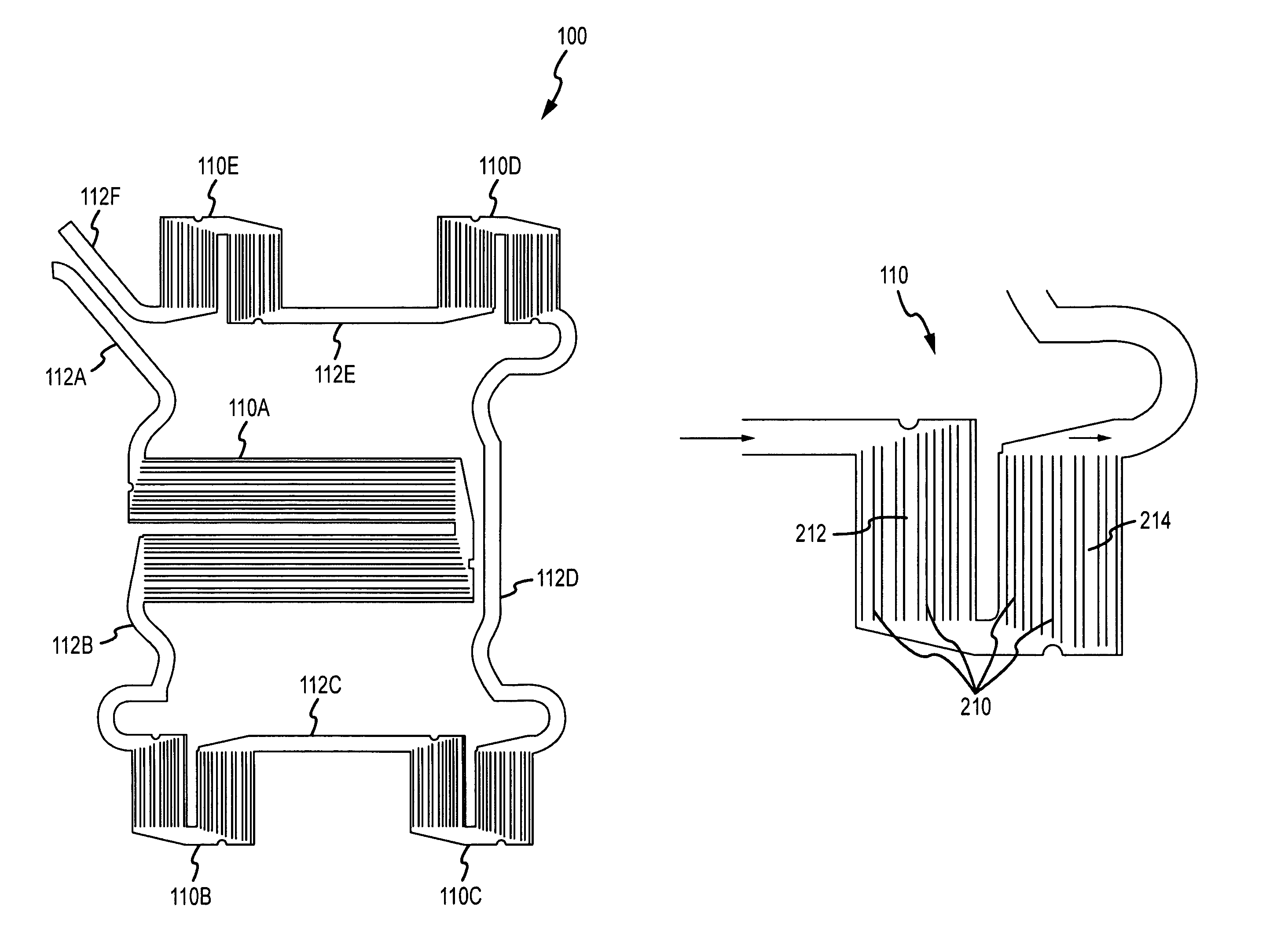
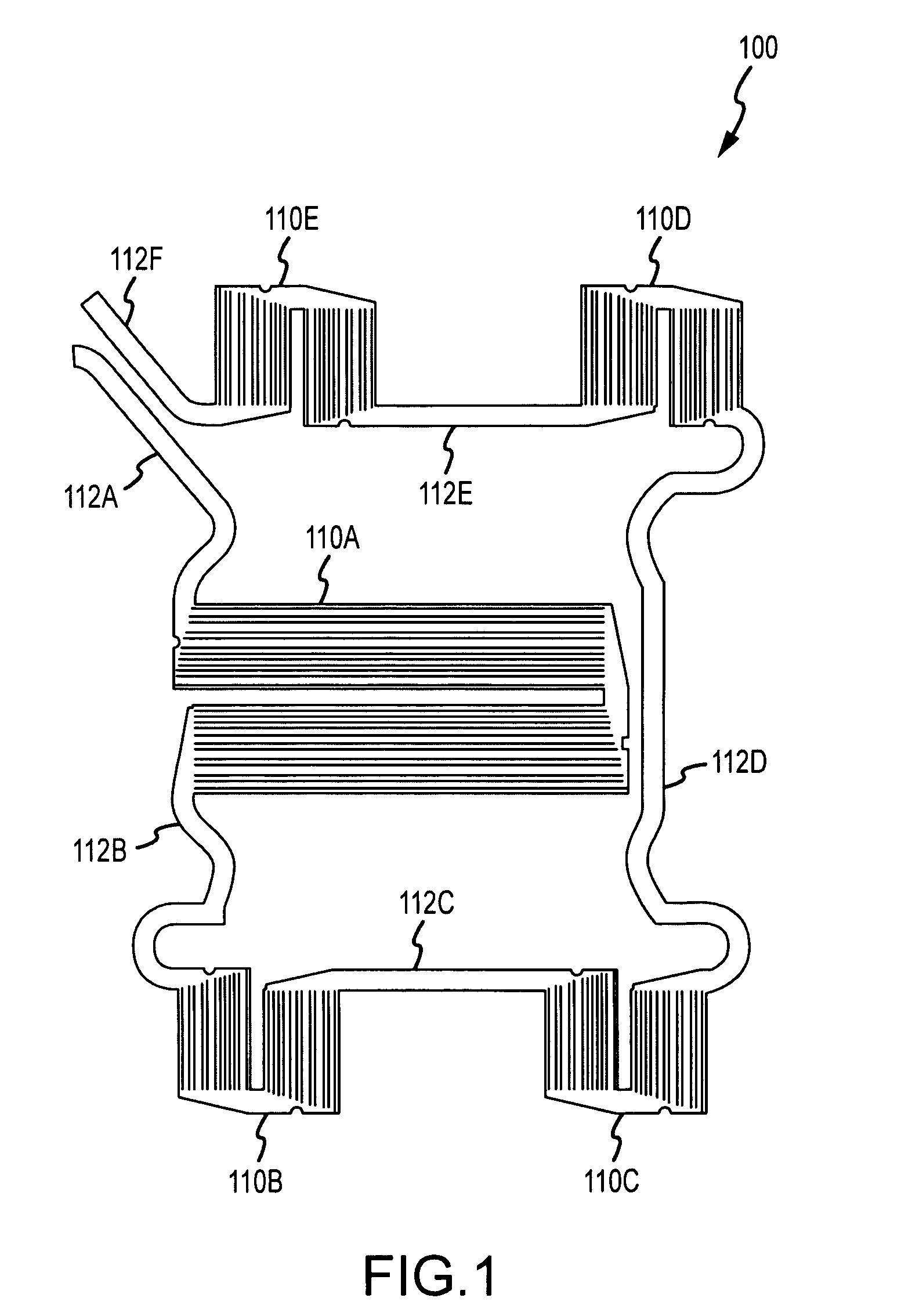
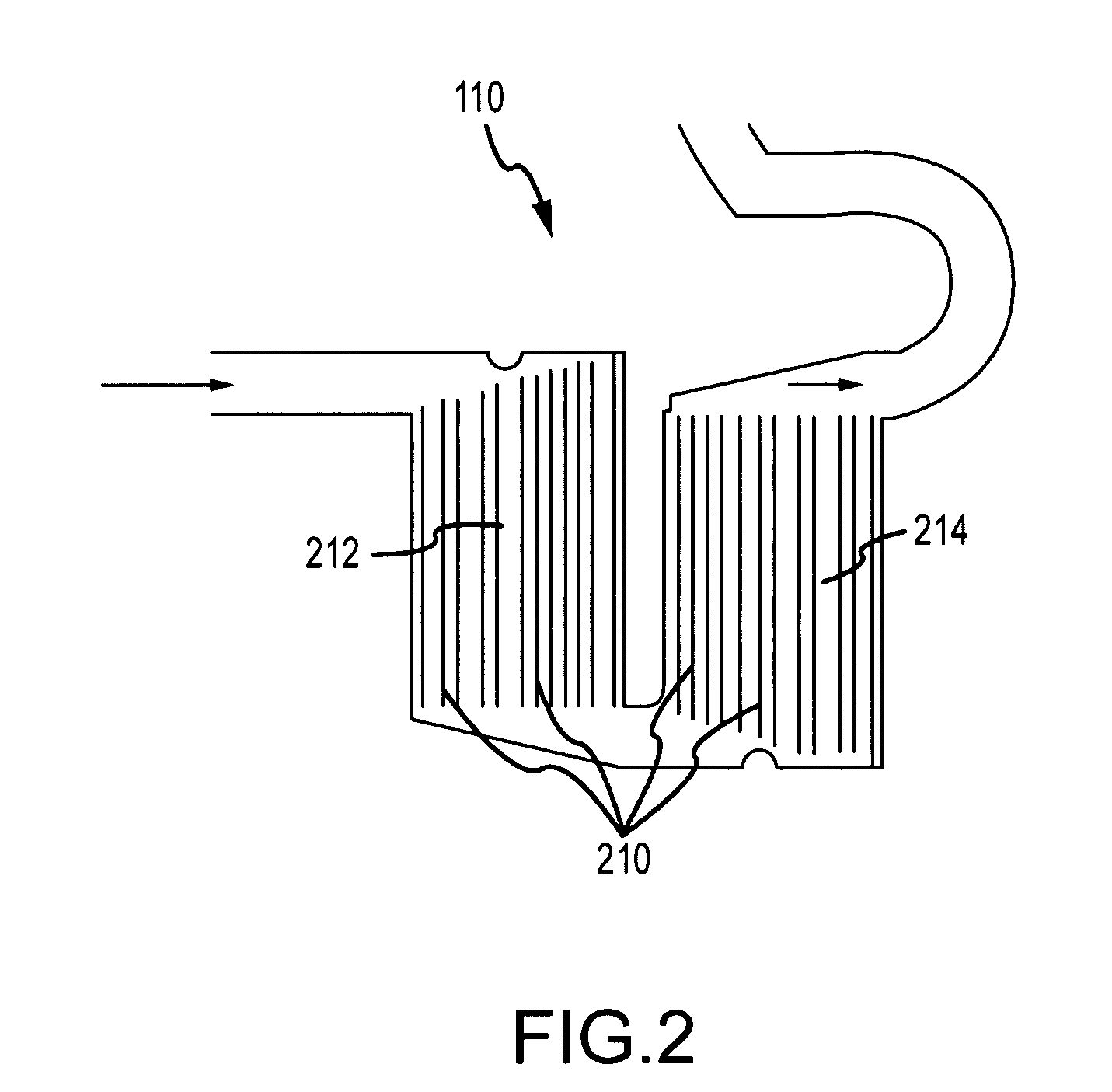
[0004]In a representative aspect, the present invention includes a system and method for improved equipment cooling. The system comprises a fluid cooled coldplate and / or the like. In accordance with various aspects of the present invention, the system may provide cooling regardless of the orientation of the coldplate during operation. The coldplate may be designed to provide substantially uniform fluid velocity throughout the coldplate thereby reducing localized regions of trapped fluid and increasing the cooling efficiency of the system.

Problems solved by technology

Prior attempts to address this problem have resulted in coldplates that have difficulty maintaining uniform fluid velocity in the flow region due to gravitational effects when the coldplate is positioned in multiple orientations.
Regions also develop where fluid velocity in the flow region is greatly reduced, affecting the ability of the coldplate to transfer heat.
Additionally, coldplates with unidirectional fluid flow have large local temperature deltas.

Method used


Image

  • Multi-orientation single or two phase coldplate with positive flow characteristics
  • Multi-orientation single or two phase coldplate with positive flow characteristics
  • Multi-orientation single or two phase coldplate with positive flow characteristics

Examples


Embodiment Construction

[0012]The following representative descriptions of the present invention generally relate to exemplary embodiments and the inventors' conception of the best mode, and are not intended to limit the applicability or configuration of the invention in any way. Rather, the following description is intended to provide convenient illustrations for implementing various embodiments of the invention. As will become apparent, changes may be made in the function and / or arrangement of any of the elements described in the disclosed exemplary embodiments without departing from the spirit and scope of the invention.

[0013]The present invention may be described herein in terms of conventional coldplates, flow passages, and fluids. Further, the present invention may employ any number of conventional techniques for fluid cooling and / or the like.

[0014]It should be appreciated that coldplates in accordance with various aspects of the present invention may comprise any number of conventional materials inc...


PUM


Abstract

An apparatus, system and method for multi-orientation single or two phase coldplate with positive flow characteristics is disclosed. In representative embodiments and applications, the present invention generally provides improved methods and systems for cooling through fluid cooled coldplates.

Description

RELATED APPLICATIONS[0001]This application claims the benefit of U.S. Provisional Patent Application Ser. No. 60 / 867,717 filed in the United States Patent and Trademark Office on Nov. 29, 2006.BACKGROUND OF INVENTION[0002]Various techniques are used to facilitate cooling of mechanical and electronic equipment. The ability to provide sufficient cooling to components that experience heat gain is essential to proper function and product reliability. Common methods of cooling typically include forced movement of ambient air, radiators, heatsinks, and use of cooling liquids. Cooling may be as simple as using a fan to move relatively cooler air over a component that has experienced.[0003]Prior attempts to address this problem have resulted in coldplates that have difficulty maintaining uniform fluid velocity in the flow region due to gravitational effects when the coldplate is positioned in multiple orientations. Regions also develop where fluid velocity in the flow region is greatly redu...

Claims


Application Information

Patent Timeline
Patent Type & Authority Patents(United States)
IPC IPC(8): F28F3/12F28D15/02
CPCF28D15/0233F28D15/0275
Inventor WYATT, WILLIAM G.PRUETT, JAMES A.SCHWARTZ, GARY
Owner RAYTHEON CO
Learn More