
Microwave resonator configured by composite right/left-handed meta-material and antenna apparatus provided with the microwave resonator

a technology of composite right/left meta-materials and microwave resonators, which is applied in the field of microwave resonators, can solve the problems of not being suitable for an increase in the size of the antenna, unable to obtain resonance operation, and disadvantageous reduction of group velocity

Active Publication Date: 2015-02-03
JAPAN SCI & TECH CORP
View PDF15 Cites 12 Cited by
  • Summary
  • Abstract
  • Description
  • Claims
  • Application Information

AI Technical Summary

Benefits of technology

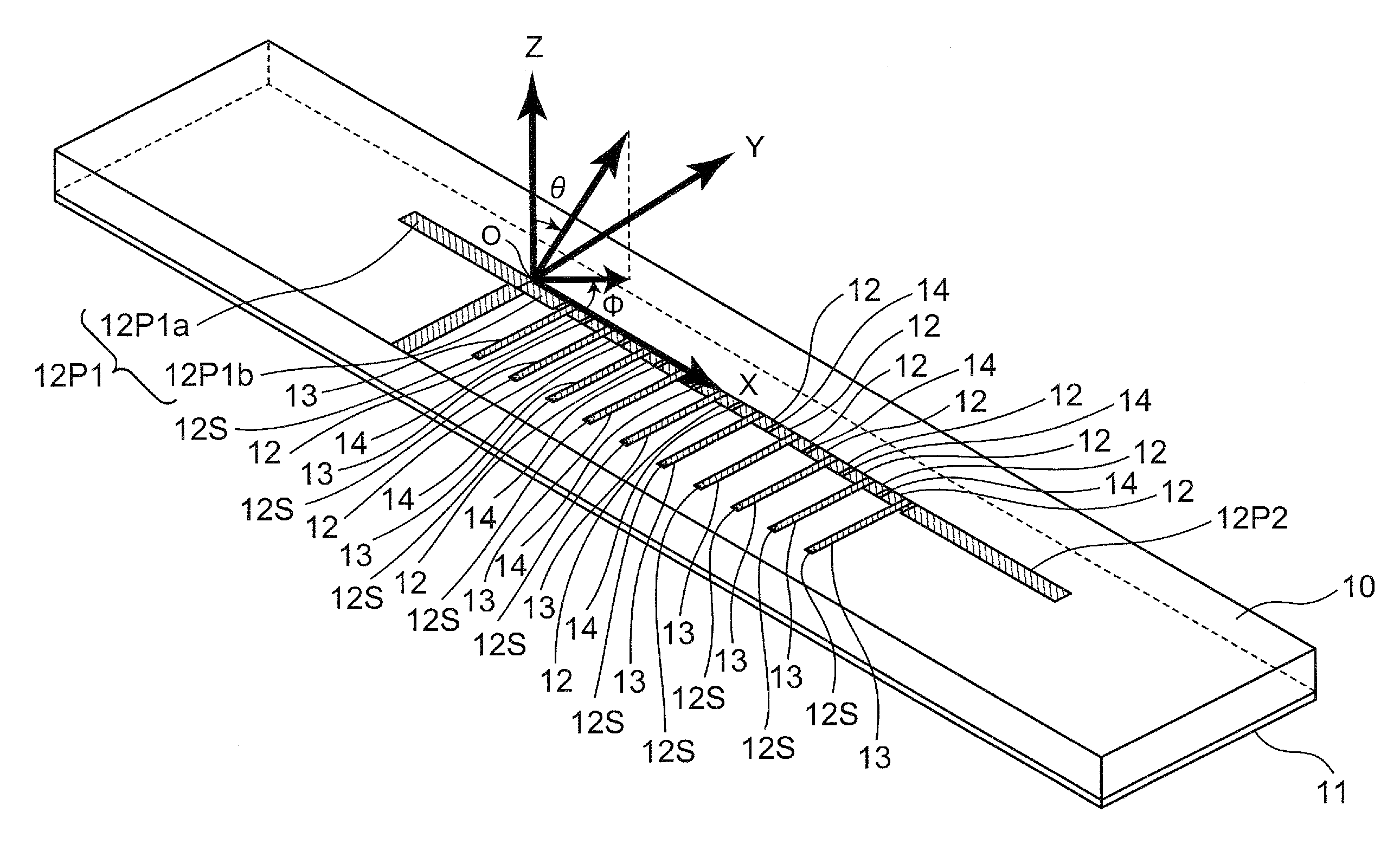
[0039]According to the microwave resonator of the present invention, the first reflective impedance circuit that is connected to the first port of the microwave transmission line and operates in a manner that the impedance when the first reflective impedance circuit is seen from the first port becomes the first impedance at the predetermined operating frequency, and the second reflective impedance circuit that is connected to the second port of the microwave transmission line and operates in a manner that the impedance when the second reflective impedance circuit is seen from the second port becomes the second impedance at the operating frequency are provided. The imaginary part of the first impedance and imaginary part of the second impedance have signs different from each other, and the magnitude of the imaginary part of the first impedance and the magnitude of the imaginary part of the second impedance are substantially equal to each other. Therefore, the zeroth-order resonator in the double resonance state in which the series resonance and the parallel resonance coexist between the state in which only the series resonance of the series branch of the unit cells that constitute the microwave transmission line is dominant and the state in which only the parallel resonance of the parallel branch is dominant can be actualized.
[0040]In addition, according to the antenna apparatus of the present invention, the microwave resonator of the present invention and the feeding circuit that is connected to the first reflective impedance circuit or the second reflective impedance circuit, and outputs the microwave signal received by the microwave resonator are provided. Therefore, the polarization direction of the microwave signal to be received can be set in an arbitrary direction between the direction parallel to the series branch and the direction parallel to the parallel branch of the unit cells that constitute the microwave transmission line.
[0041]Further, according to an antenna apparatus of the present invention, the first reflective impedance circuit has the first impedance changing means that changes the first impedance, and the second reflective impedance circuit has the second impedance changing means that changes the second impedance. The antenna apparatus further includes the control means for controlling the first and second impedance changing means to change the polarization direction of the microwave signal received by the microwave resonator. Therefore, the polarization direction can be changed so that, for example, the received power of the received microwave signal becomes maximized.
[0042]Still further, the band-pass filter apparatus of the present invention includes the microwave resonator of the present invention. The first reflective impedance circuit has the first impedance changing means that changes the first impedance, and the second reflective impedance circuit has the second impedance changing means that changes the second impedance. The band-pass filter apparatus further includes the control means for controlling the first and second impedance changing means to change the band-pass frequency of the band-pass filter apparatus. Therefore, the band-pass filter apparatus having an arbitrary band-pass filter frequency between the series resonance frequency and the parallel resonance frequency can be actualized.
[0043]In addition, the band-stop filter apparatus of the present invention has the microwave resonator of the present invention. The first reflective impedance circuit has the first impedance changing means that changes the first impedance, and the second reflective impedance circuit has the second impedance changing means that changes the second impedance. The band-stop filter apparatus further includes the control means for controlling the first and second impedance changing means to change the band-stop frequency of the band-stop filter apparatus. Therefore, the band-stop filter apparatus having an arbitrary band-stop filter frequency between the series resonance frequency and the parallel resonance frequency can be actualized.

Problems solved by technology

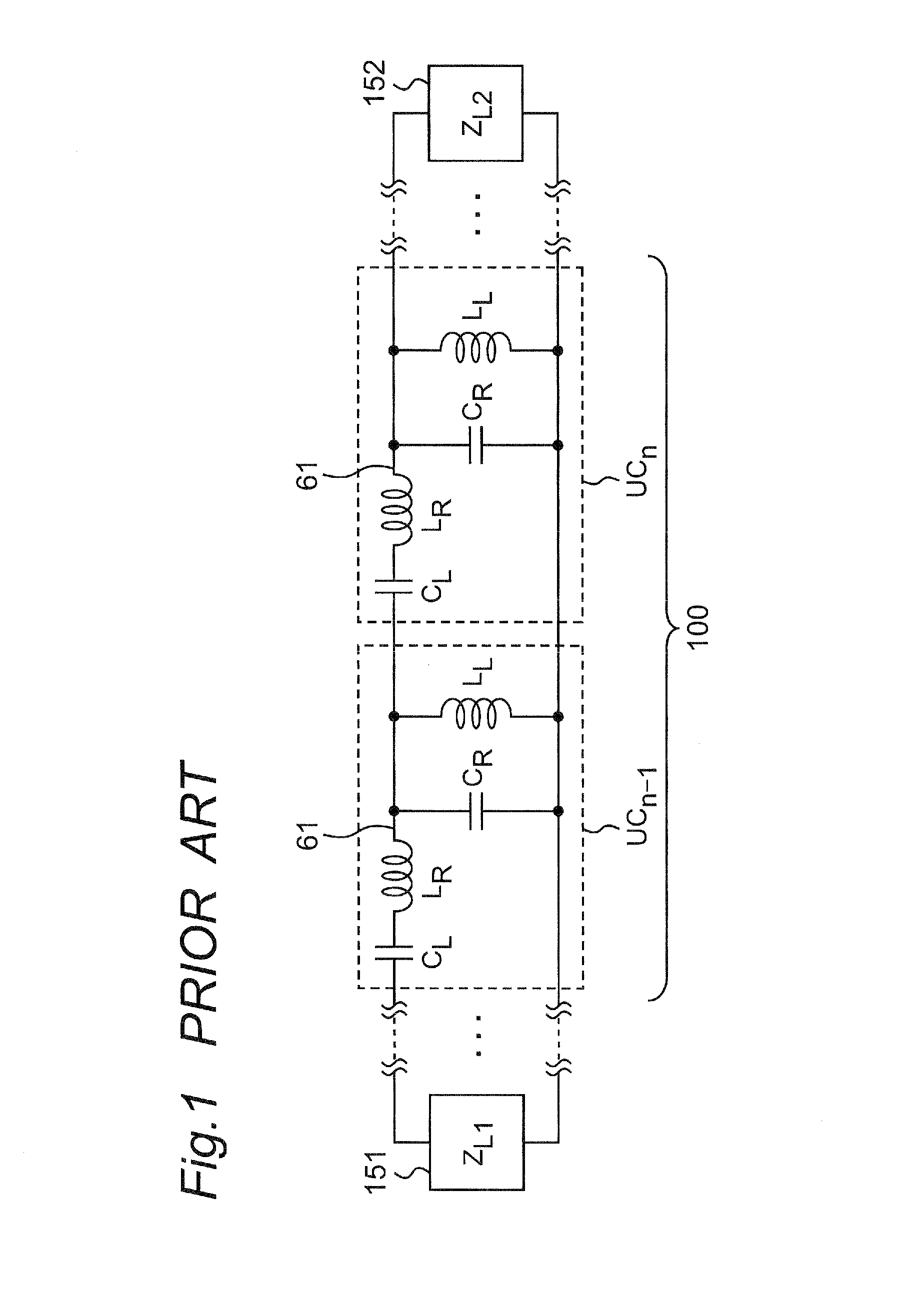
However, in the zeroth-order resonator configured by employing an unbalanced composite right / left-handed transmission line whose frequency at which the effective permittivity is zero and frequency at which the effective permeability is zero are varied, the group velocity also disadvantageously becomes zero by its nature at the frequency at which the phase constant is zero on the dispersion curve that represents the propagation characteristics of the line.
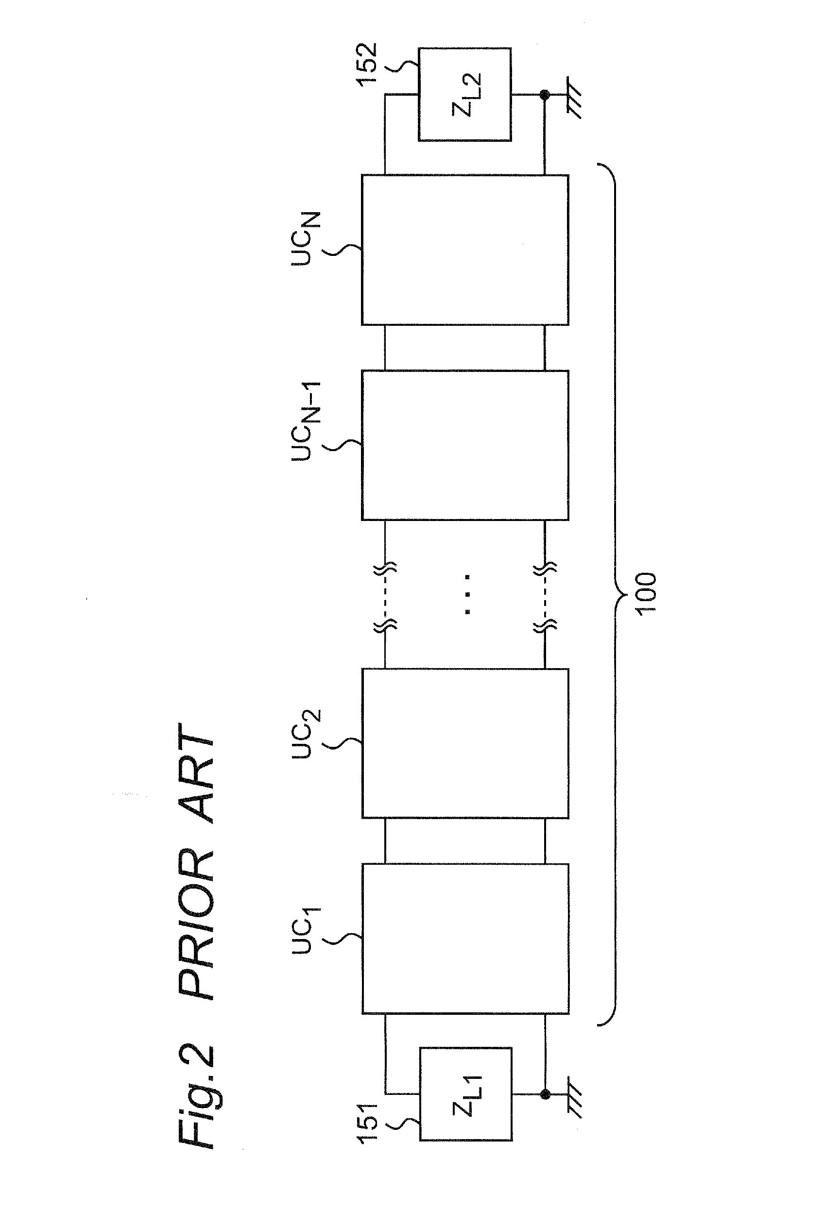
Accordingly, there has been such a problem that, when the number of unit cells that constitute the resonator is increased (resonator is increased in size), no resonance operation can be obtained because the signal cannot be propagated along the resonator.
In practice, many of the zeroth-order resonators with use of the unbalanced composite right / left-handed transmission line proposed up to now are configured to include a comparatively smaller number of unit cells, and they are not suitable for an increase in the size of the antenna.

Method used


Image

  • Microwave resonator configured by composite right/left-handed meta-material and antenna apparatus provided with the microwave resonator
  • Microwave resonator configured by composite right/left-handed meta-material and antenna apparatus provided with the microwave resonator
  • Microwave resonator configured by composite right/left-handed meta-material and antenna apparatus provided with the microwave resonator

Examples


Embodiment Construction

[0102]Preferred embodiments of the present invention will be described hereinafter with reference to the drawings. In the preferred embodiments, components similar to each other are denoted by the same reference numerals.

[0103]In addition, in the present specification, mathematical numbers inserted between square brackets in which mathematical expressions are inputted in image form, and mathematical expression numbers inserted between round brackets in which mathematical expressions are inputted in symbolic form are used in mixture. In addition, it is defined that mathematical expression numbers are used given to the tail parts of seriated mathematical expressions in the form of “Expression (1)” (there are some mathematical expressions to which no mathematical expression numbers are attached) in the present specification.

1. Basic Configuration of Composite Right / Left-Handed Transmission Line 100

[0104]The basic configuration of the composite right / left-handed transmission line 100 em...


PUM


Abstract

A reflective impedance element is connected to a port of a composite right / left-handed transmission line, and operates at a predetermined operating frequency so that an impedance when the reflective impedance element is seen from the port becomes a pure imaginary number jB. A reflective impedance component is connected to a port of the composite right / left-handed transmission line, and operates at the predetermined operating frequency so that an impedance when the reflective impedance element is seen from the port becomes −jB.

Description

TECHNICAL FIELD[0001]The present invention relates to a meta-material (artificial structure apparatus) having a function to permit or inhibit the propagation of electromagnetic waves, and relates to a microwave resonator configured to include a composite right / left-handed meta-material whose effective permittivity assumes any one of positive, negative and zero values and whose effective permeability assumes any one of positive, negative and zero values on the other hand, an antenna apparatus with use of the microwave resonator, and a band-pass filter apparatus and a band-stop filter apparatus with use of the microwave resonator. It is noted in the present specification that the microwaves mean, for example, microwaves in the frequency bands of not lower than the UHF (Ultra High Frequency) band, millimeter waves, quasi-millimeter waves, and terahertz waves.BACKGROUND ART[0002]The meta-material is an artificial structure that behaves unlike materials in the natural world with respect ...

Claims


Application Information

Patent Timeline
Patent Type & Authority Patents(United States)
IPC IPC(8): H01Q1/50H01P1/203H01P7/08H01Q15/00H03H7/01
CPCH03H7/0138H01P1/203H01P7/082H01Q15/0086H03H7/0115
Inventor UEDA, TETSUYAHAIDA, GOUKIYAMAMOTO, SHINTARO
Owner JAPAN SCI & TECH CORP
Learn More