
Oscillator apparatus and method with wide adjustable frequency range

a technology of oscillator and frequency range, which is applied in the direction of pulse generator, pulse generation by vacuum tubes, pulse technique, etc., can solve the problems of inability to operate over ultra wide synchronous frequency range and temperature range as desired, and existing approaches that use more costly and complex integrated circuit devices

Active Publication Date: 2014-11-18
CRANE ELECTRONICS INC
View PDF84 Cites 15 Cited by
  • Summary
  • Abstract
  • Description
  • Claims
  • Application Information

AI Technical Summary

Benefits of technology

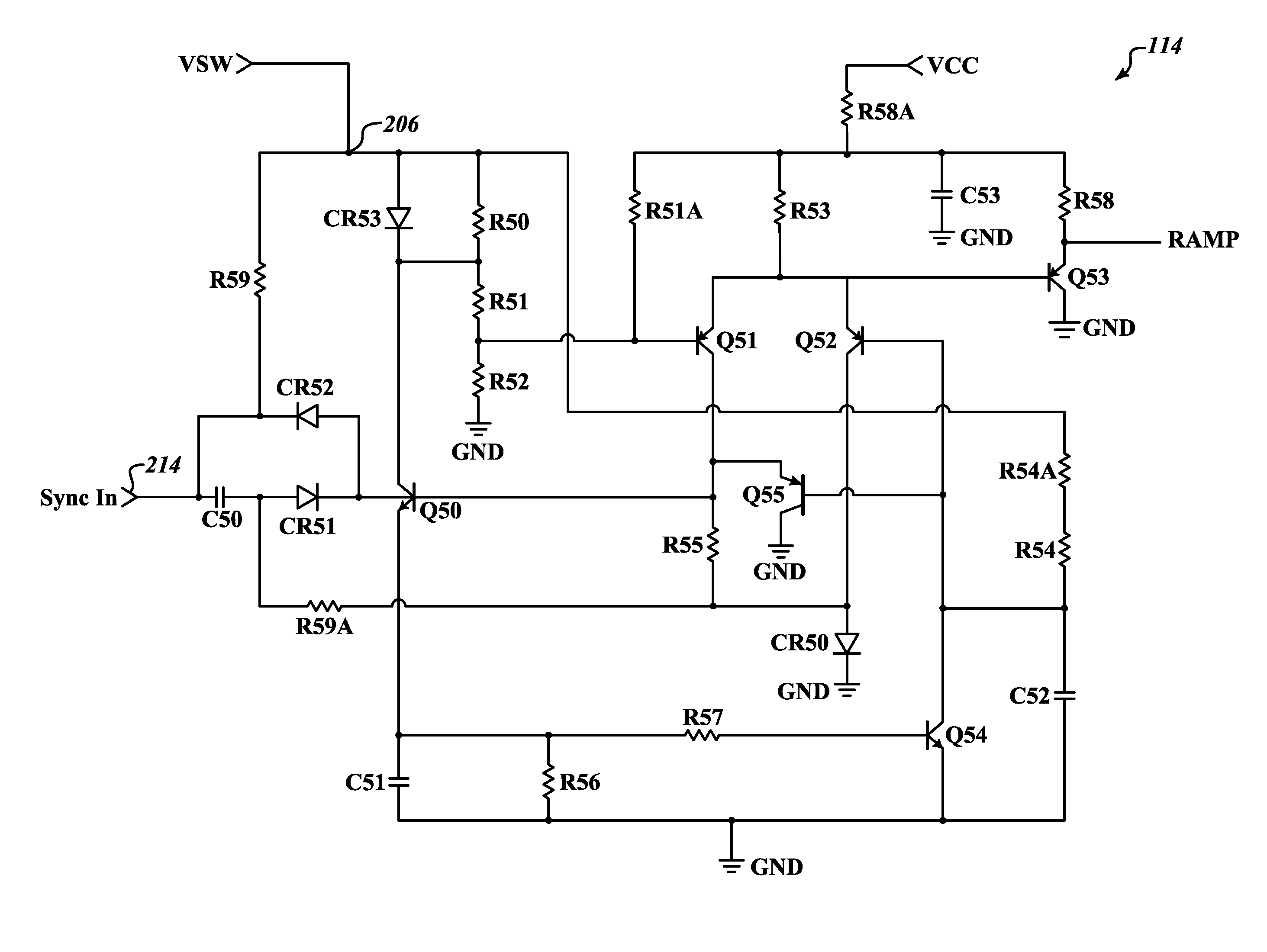
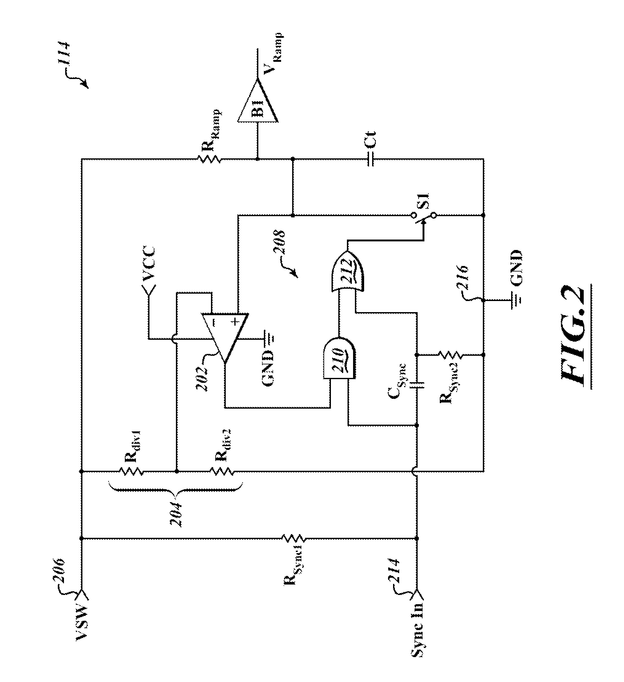
[0010]The approaches described herein to generate a periodic ramp oscillator signal may advantageously provide one or more of: 1) the oscillator is self oscillating and requires no start up input; 2) the slope of the ramp is modulated by an external signal and is linear over a wide range of operating conditions of input signal range & temperature; 3) the oscillator signal output can be synchronized to an external clock signal input; 4) the oscillator signal output synchronizes to the external signal input up to two times the self oscillation frequency of the oscillator; and / or 5) method uses less complex, lower cost discrete semiconductor components, chip resistors and capacitors.
[0015]The oscillator may further include a level shifting diode electrically coupling a control transistor resistor to a ground to level shift the control transistor resistor reducing a voltage required to turn on the control transistor. The ramp timing resistance may include a first ramp resistor and a second ramp resistor electrically coupled in series with the first ramp resistor between the voltage input terminal and the ramp timing capacitor.

Problems solved by technology

In contrast, existing approaches utilize more costly and complex integrated circuit devices, such as comparators / operational amplifiers with additional components or a custom designed complex integrated circuit.
Existing approaches also appear to fail to operate over an ultra wide synchronous frequency range and temperature range as desired, with external slope modulation of the ramp oscillator signal.

Method used


Image

  • Oscillator apparatus and method with wide adjustable frequency range
  • Oscillator apparatus and method with wide adjustable frequency range
  • Oscillator apparatus and method with wide adjustable frequency range

Examples


Embodiment Construction

[0029]In the following description, certain specific details are set forth in order to provide a thorough understanding of various disclosed embodiments. However, one skilled in the relevant art will recognize that embodiments may be practiced without one or more of these specific details, or with other methods, components, materials, etc. In other instances, well-known structures associated with power conversion topologies have not been shown or described in detail to avoid unnecessarily obscuring descriptions of the embodiments.

[0030]Unless the context requires otherwise, throughout the specification and claims which follow, the word “comprise” and variations thereof, such as, “comprises” and “comprising” are to be construed in an open, inclusive sense, that is as “including, but not limited to.”

[0031]Reference throughout this specification to “one embodiment” or “an embodiment” means that a particular feature, structure or characteristic described in connection with the embodimen...


PUM


Abstract

An oscillator formed from low cost discrete semiconductors and passive devices creates a linear periodic ramp of constant frequency with ramp slope based on an external voltage signal. Parameters are stable over a wide range of temperatures and variations of transistor parameters that normally degrade in extreme environments. The oscillator period can be phase and frequency synchronized to an external clock source over a wide range of frequencies. The oscillator ramp generator phase can be synchronized on a cycle by cycle basis for incorporation in power converters employing spread spectral EMI reduction techniques, multi-converter systems employing clock interleaving for distribution bus filter optimization, and resonant mode converters employing zero voltage switching techniques. Oscillator ramp rate is independent of frequency and can be synchronized to DC (inhibit) for use in ultra low power burst mode power conversion.

Description

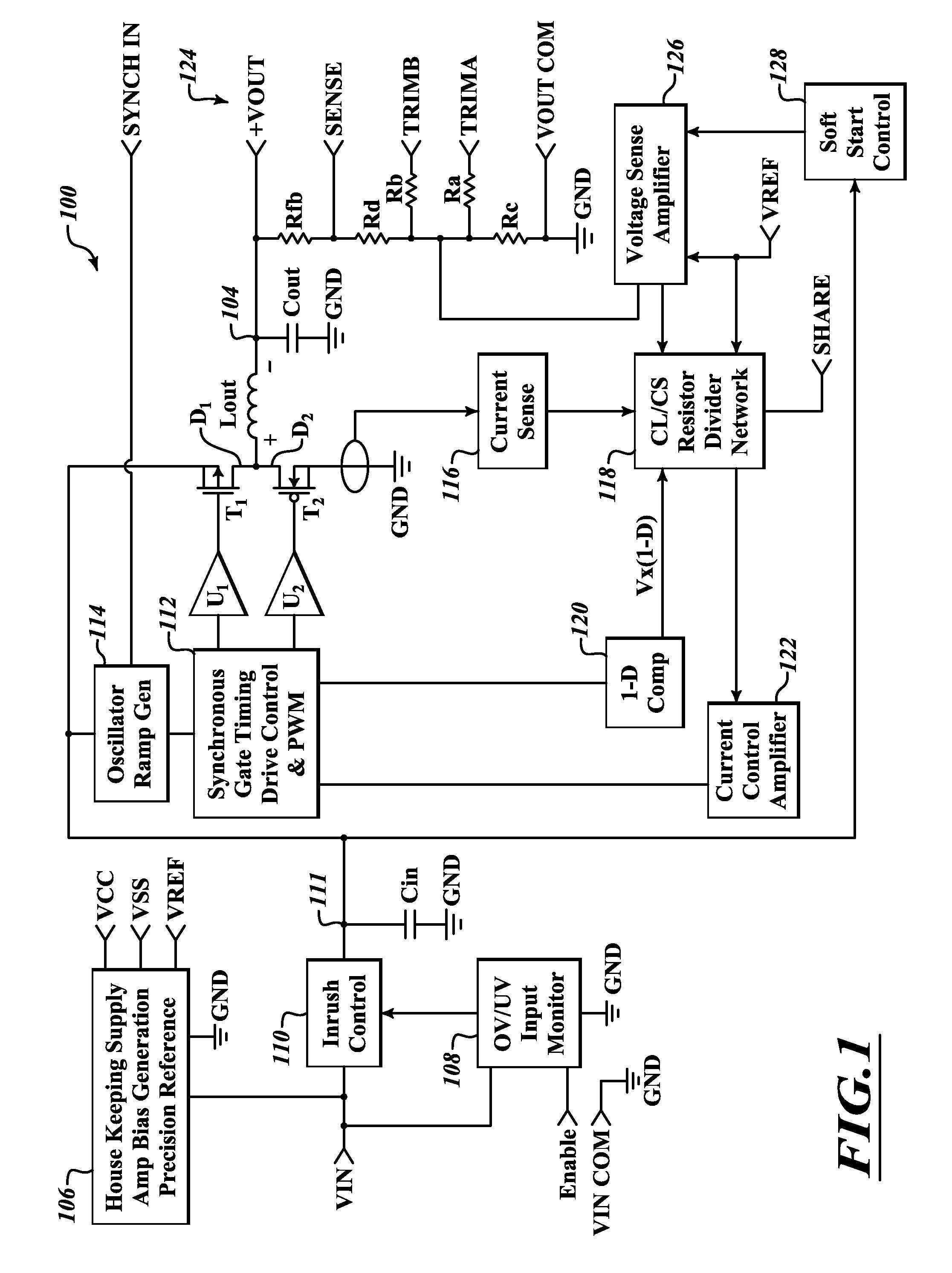
BACKGROUND[0001]1. Technical Field[0002]This disclosure is generally related to oscillators, which may, for example, be employed in power converters and other devices.[0003]2. Description of the Related Art[0004]Power converters are used to transform electrical energy, for example converting between alternating current (AC) and direct current (DC), adjusting (e.g., stepping up, stepping down) voltage levels and / or frequency.[0005]Power converters take a large variety of forms. One of the most common forms is the switched-mode power converter or supply. Switched-mode power converters employ a switching regulator to efficiently convert voltage or current characteristics of electrical power. Switched-mode power converters typically employ a storage component (e.g., inductor, transformer, capacitor) and a switch that quickly switches between full ON and full OFF states, minimizing losses. Voltage regulation may be achieved by varying the ratio of ON to OFF time or duty cycle. Various to...

Claims


Application Information

Patent Timeline
Patent Type & Authority Patents(United States)
IPC IPC(8): H03B5/24H03B5/04H03K4/12H03K3/0231H03K3/354H03K3/02
CPCH03B5/24H03K3/354H03K3/0231H03B2200/0074H03B5/04H03K4/12H02M3/156
Inventor HUGHES, RODNEY, ALAN
Owner CRANE ELECTRONICS INC
Learn More