
Calibration pattern selection based on noise sensitivity

a pattern selection and noise sensitivity technology, applied in the field of model calibration patterns, can solve the problems of enormous cost of making high-end mask sets, difficult to reproduce patterns on wafers, and large optimization problems of opc, so as to improve the accuracy and reliability of lithography apparatus/systems. the effect of predicting the imaging performance of the apparatus/system

Active Publication Date: 2014-11-11
ASML NETHERLANDS BV
View PDF6 Cites 12 Cited by
  • Summary
  • Abstract
  • Description
  • Claims
  • Application Information

AI Technical Summary

Benefits of technology

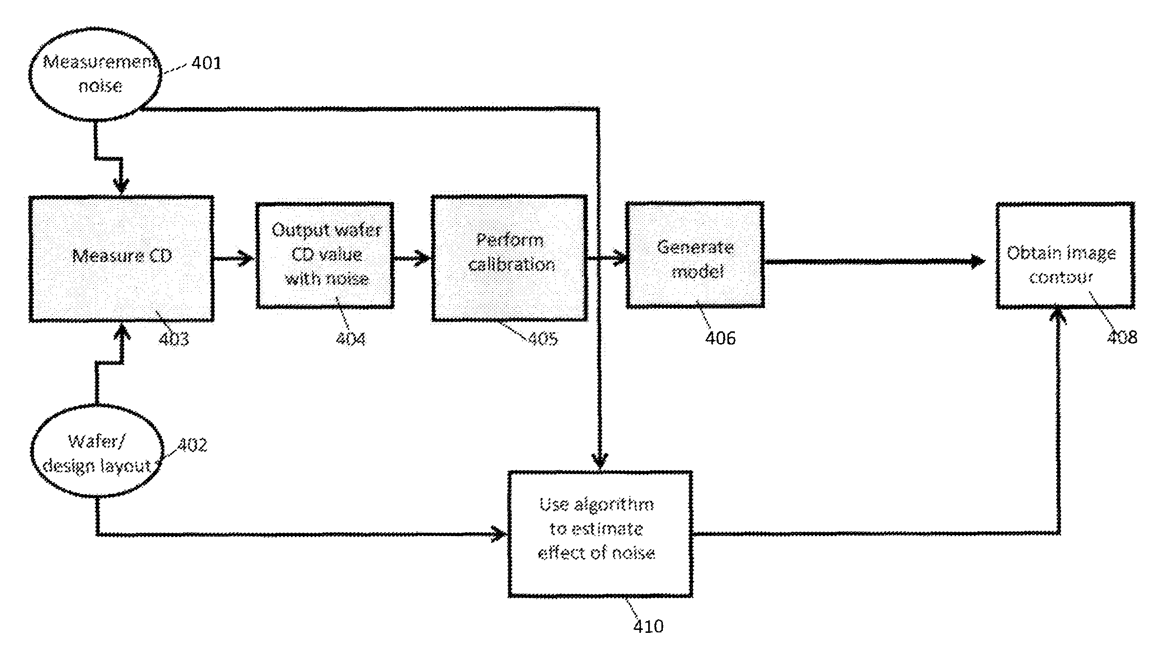
The patent provides methods and systems for selecting the best pattern set to calibrate a lithography model, so that it can better predict the performance of a lithography apparatus. This is done by modeling sensitivity to measurement noise and using a set of calibration patterns. These patterns can be either dedicated for testing or are drawn from a design layout. The method and system can be used for both physical and virtual lithography platforms. The calibration patterns are defined as "full-chip gauges," which include one or more patterns that represent the expected behavior of the full design layout or chip. The method also involves identifying a model of the lithographic process and a set of patterns for calibration, as well as estimating measurement noise associated with the patterns. Overall, this approach helps improve the accuracy and reliability of predicting the performance of a lithography process without being too expensive or time-consuming.

Problems solved by technology

These rules are set by processing and design limitations.
In general, the smaller k1, the more difficult it becomes to reproduce a pattern on the wafer that resembles the shape and dimensions planned by a circuit designer in order to achieve particular electrical functionality and performance.
The OPC is essentially a very large optimization problem.
In the general case, there is no closed-form solution to this problem, and OPC vendors use an approximate, iterative process that does not always resolve all possible weaknesses on a layout.
This is driven by the enormous cost of making high-end mask sets, which run in the multi-million dollar range, as well as by the impact on turn-around time by reworking or repairing actual masks once they have been manufactured.
Such patterns are often insufficient for calibration or too computationally-intensive due to redundancy.
In particular, for some parameters, all the patterns may be quite insensitive thus it may be difficult to determine the parameter values due to measurement inaccuracies.
While on the other hand, many patterns may have very similar responses to parameter variations thus some of them are redundant and wafer measurements on these redundant patterns waste a lot of resources.
Collecting such metrology data is often time-consuming and expensive.
However, in modern lithography, the optical range of influence (ambit) is much larger than the typical test structure and therefore it is no longer true that accurate modeling of a pre-selected number of relatively small test patterns guarantees accurate prediction of these patterns in their actual circuit environments.
Most of the geometry-based approaches are somewhat heuristic in nature, and are often prone to one or both of the following drawbacks.
Due to a lack of discriminating patterns, patterns can be poorly determined or they can exhibit a high degree of degeneracy with other parameters.
Either way, the methods routinely fail to properly describe the change in imaging behavior outside the conditions included in the model characterization.
For some of the physical / chemical properties and associated model parameters that are captured by the calibration method, the approach is not economical and too many measurements provide essentially redundant information.
Additionally, the current gauge selection methods are not easily generalizable.
Most of the traditional methods fail to provide a comprehensive way to select the gauges once their characterization is done.

Method used


Image

  • Calibration pattern selection based on noise sensitivity
  • Calibration pattern selection based on noise sensitivity
  • Calibration pattern selection based on noise sensitivity

Examples


Embodiment Construction

[0032]The present invention will now be described in detail with reference to the drawings, which are provided as illustrative examples of the invention so as to enable those skilled in the art to practice the invention. Notably, the figures and examples below are not meant to limit the scope of the present invention to a single embodiment, but other embodiments are possible by way of interchange of some or all of the described or illustrated elements. Moreover, where certain elements of the present invention can be partially or fully implemented using known components, only those portions of such known components that are necessary for an understanding of the present invention will be described, and detailed descriptions of other portions of such known components will be omitted so as not to obscure the invention. Embodiments described as being implemented in software should not be limited thereto, but can include embodiments implemented in hardware, or combinations of software and...


PUM


Abstract

The preset invention provides methods, systems and computer program product for selection of an optimum set of patterns to calibrate a lithography model so that the model can predict imaging performance of a lithography apparatus / system more accurately and reliably without being prohibitively expensive in terms of using computational and metrology resources and time. The method is based on modeling sensitivity of the calibration patterns to measurement noise. In one aspect of the present invention, a method is disclosed, comprising: identifying a model of at least a portion of a lithographic process; identifying a set of patterns for calibrating the model; and, estimating measurement noise associated with the set of patterns.

Description

CROSS-REFERENCE TO RELATED APPLICATIONS[0001]This application claims priority to U.S. Provisional Application No. 61 / 553,105 filed Oct. 28, 2011, which is incorporated herein by reference in its entirety.COPYRIGHT AUTHORIZATION[0002]A portion of the disclosure of this patent document contains material which is subject to copyright protection. The copyright owner has no objection to the facsimile reproduction by anyone of the patent disclosure, as it appears in the Patent and Trademark Office patent files or records, but otherwise reserves all copyright rights whatsoever.FIELD OF THE INVENTION[0003]The technical field of the present invention relates generally to patterns for model calibration associated with a lithography process, and more specifically to selecting an optimal set of patterns from a larger set of patterns.BACKGROUND OF THE INVENTION[0004]Lithographic apparatuses can be used, for example, in the manufacture of integrated circuits (ICs). In such a case, the mask may co...

Claims


Application Information

Patent Timeline
Patent Type & Authority Patents(United States)
IPC IPC(8): G06F17/50
CPCG03F1/70G03F1/36
Inventor BRUGUIER, ANTOINE JEANSHAO, WENJINLAN, SONG
Owner ASML NETHERLANDS BV
Learn More