
Fiber wadding for filling bone defects

a fiber wadding and bone defect technology, applied in the field of bioactive materials, can solve the problems of low strength and toughness, difficult machined, and inability to show osteogenic ability of biodegradable polymers, and achieve the effects of low viscosity, high viscosity, and low viscosity

Active Publication Date: 2014-10-07
NAGOYA INSTITUTE OF TECHNOLOGY +1
View PDF2 Cites 20 Cited by
  • Summary
  • Abstract
  • Description
  • Claims
  • Application Information

AI Technical Summary

Benefits of technology

[0037]A spinning solution may be further combined with a calcium carbonate to form a slurry (spinning slurry). This helps to speedup (acceleration) the step of soaking the electrospun article in a buffer solution that is supersaturated with hydroxyapatite to form an absorbable hydroxyapatite thereon. The absorbable hydroxyapatite helps to confer higher initial cellular adhesion. The amount of the calcium carbonate is possibly 60 percent by weight or less, because the calcium carbonate, if added in an amount of more than 60 percent by weight, maybe difficult to mix with the solution to give a homogeneous slurry. However, the calcium carbonate, if added in an amount less than 10 percent by weight, may not exhibit its advantageous effects remarkably. The solution or slurry may further include one or more inorganic substances which are usable in viva without problems. Examples of such inorganic substances include hydroxyapatite, tricalcium phosphate, calcium sulfate, sodium phosphate, sodium hydrogen phosphate, calcium hydrogen phosphate, octacalcium phosphate, tetracalcium phosphate, calcium pyrophosphate, and calcium chloride.
[0038]In accordance with embodiments of the invention, a material for filling bone defects can also be a substance containing a biodegradable resin as a principal component and further containing or bearing a siloxane. This substance may be prepared by preparing calcium carbonate micro-particles bearing siloxane dispersed therein (Si—CaCO3), typically by the method described in Japanese Unexamined Patent Application Publication (JP-A) No. 2008-100878; and mixing 60 percent by weight or less of the Si—CaCO3 microparticles with PLA. The amount of the Si—CaCO3 microparticles is preferably from 10 to 60 percent by weight relative to the PLA, as in the calcium carbonate. To uniformly disperse the micro-particles, the substance is preferably prepared by kneading the PLA and Si—CaCO3 micro-particles in predetermined proportions in a heating kneader to give a composite. The composite is then dissolved in the solvent to give a spinning solution.
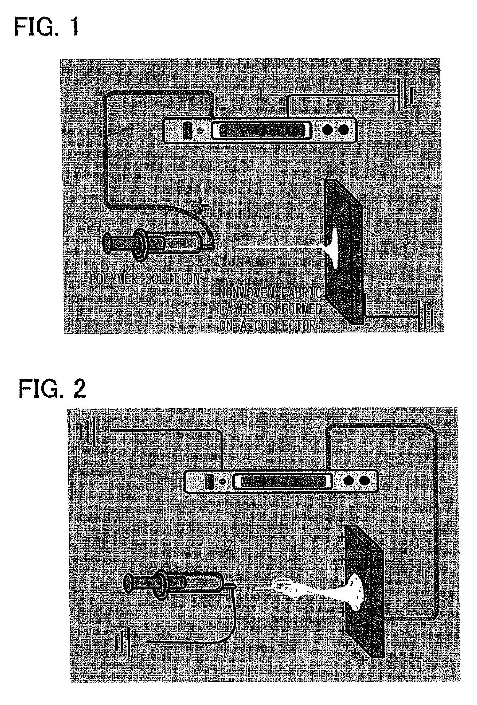
[0039]According to a common electrospinning technique, as illustrated in FIG. 1, a charge is applied by a voltage supply 1 to a nozzle of a syringe 2. In this manner, a positive charge is applied to a spinning solution; and the solution is slowly extruded from the tip of the nozzle. When the effect of electric field becomes larger than the surface tension, the solution is stretched into fibers and travels toward a collector 3 which is connected with a ground electrode. On the way to the collector 3, the solvent of the solution evaporates, thereby forming a thin layer of nonwoven fabric of fibers. This technique, however, does not produce a three-dimensional structure, even if one modifies the spinning conditions (such as the concentration of the spinning solution, the type of solvent contained in the solution, the supply speed of the solution, the spinning time, the applied voltage, and the distance between the nozzle and the collector). This is because the residual solution and the resin deposited on the collector 3 are charged by themselves and repel each other. The repulsion impedes the deposition in a thickness direction. In this connection, the fibrous resin derived from the solution deposits on the collector 3 would have most solvent evaporated. However, a trace amount of the solution deposits intact (i.e., containing the solvent) on the collector 3.
[0040]In contrast, according to embodiments of the present invention, as illustrated in FIG. 2, a three-dimensional structure of a fiber wadding can be formed by carrying out electrospinning while grounding the nozzle of the syringe 2 (i.e., without applying a charge thereto). At the same time, a positive charge is applied to the collector 3. According this technique, if a regular spinning solution is slowly extruded from the tip of the nozzle, the spinning solution would fall as droplets, because the solution is not charged. However, when the spinning solution further contains a liquid, such as water, having a greater relative dielectric constant than that of the biodegradable resin, the liquid may be affected by the electric field, and the spinning solution may be drawn toward the collector by the action of polarization. In this case, the spinning solution is not charged by itself and readily forms three-dimensional deposits on the collector 3, without suffering from electrostatic repulsion. In this process, the liquid (solution) may be divided into two or more strands and drawn from the nozzle of the syringe 2 toward the collector 3. These strands are entangled to form a flocculent three-dimensional structure on the collector 3.
[0041]To allow this phenomenon to occur, however, the spinning solution should have a somewhat low viscosity. If the spinning solution has an excessively high viscosity, it may not reach the collector 3 even when affected by the electric field. Accordingly, the diameter of the fibrous substance constituting the three-dimensional structure prepared according to embodiments of the invention may be substantially controlled by the viscosity of the spinning solution. When the spinning solution has a particularly low viscosity, the fibrous substance can deposit more easily to form a three-dimensional structure and the fibrous substance would more likely have smaller fiber diameters. Typically, when a spinning solution is prepared by dissolving PLA in chloroform to give a solution, followed by adding ethanol and water thereto, the resulting fibrous substance has a fiber diameter in a range of about 0.05 μm to about 10 μm. It is acceptable not to apply a positive charge, but a negative charge, to the collector 3, as long as the spinning solution can be drawn toward the collector by the action of polarization.
[0042]The resulting three-dimensional structure of a fiber wadding may be cut into a piece of a required size, and the cut piece may be soaked in a buffer solution, containing calcium ions and phosphate ions and being saturated with respect to hydroxyapatite, to coat the surface of the fibrous skeleton with hydroxyapatite. Examples of the buffer solution for use herein include a Tris buffer solution (pH 7.2 to 7.4) containing ions at a concentration substantially equal to the inorganic ion concentration in human plasma (simulated body fluid, or SBF) and a solution (1.5 SBF) containing ions in concentrations 1.5 times those of SBF. The 1.5 SBF is more advantageous, because the fibrous substance can be coated with hydroxyapatite more rapidly.

Problems solved by technology

These substances, however, have low strength and toughness and are difficult to be machined.
The biodegradable polymers, however, do not show osteogenic ability (bone forming ability) because their biodegradability is derived from the phenomenon that they are degraded in vivo and are discharged therefrom.
In addition, there have been some reports that some of the biodegradable polymers may affect surrounding tissues because they are degraded typically into lactic acid or glycolic acid upon degradation and thus show acidity.
However, it is difficult to handle these factors.
However, it is not easy to process a dense or porous material so as to fit the dimensions of the affected area snuggly.
These techniques are therefore susceptible to improvements.
This membrane, however, is not usable as a material for filling bone defects because it has a small thickness of from 230 to 300 μm.
In addition, the bulk density of such membranes, estimated to be about 0.4 g / cm3 or more, is generally too high to be used as a material for filling bone defects.

Method used


Image

  • Fiber wadding for filling bone defects
  • Fiber wadding for filling bone defects
  • Fiber wadding for filling bone defects

Examples


example 1 and example 2

Raw Materials Used in Example 1 and Example 2

[0052]Poly(lactic acid) (PLA): PURASORB PL Poly(L-lactide), having a molecular weight of from 20×104 to 30×104, is from PURAC Biochem (a division of CSM; Netherlands). Chloroform (CHCl3): analytical grade reagent, with a purity of 99.0% or more, is from Kishida Chemical Co., Ltd., Japan. γ-Aminopropyltriethoxysilane (APTES): (TSL8331, with a purity of 98% or more, GE Toshiba Silicones Co., Ltd., Japan).

[0053]Siloxane-doped calcium carbonate (Si—CaCO3): Vaterite containing a siloxane in terms of a silicon ion content of 2.9 percent by weight and prepared by using slaked lime (Microstar T; with a purity of 96% or more; Yabashi Industries Co., Ltd., Japan), methanol (analytical grade reagent; with a purity of 99.8% or more; Kishida Chemical Co., Ltd., Japan), APTES, and carbon dioxide gas (high-purity liquefied carbon dioxide gas; with a purity of 99.9%; Taiyo Kagaku Kogyo K.K., Japan).

Electrospinning Conditions in Example 1 and Example 2

[00...

example 1

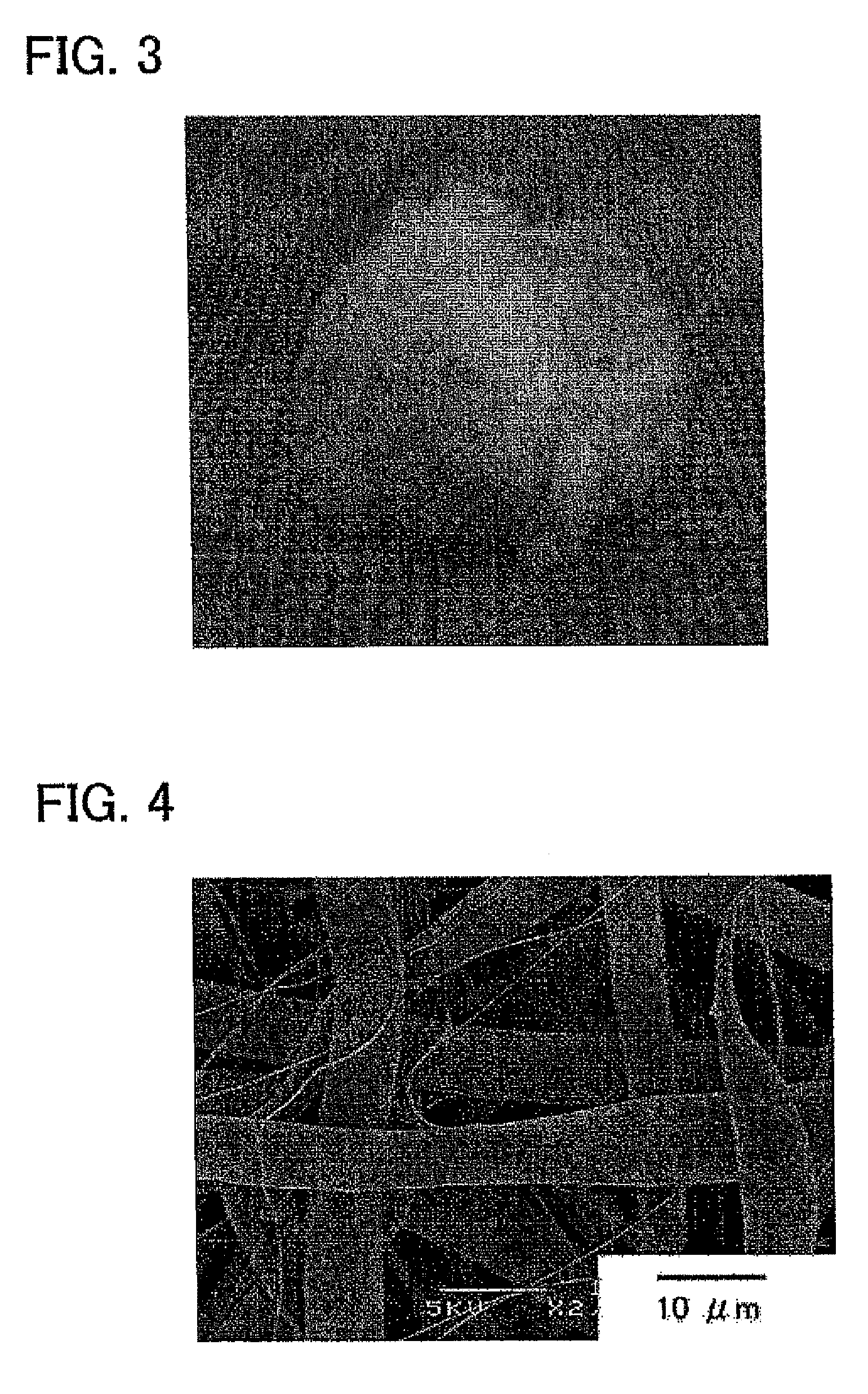
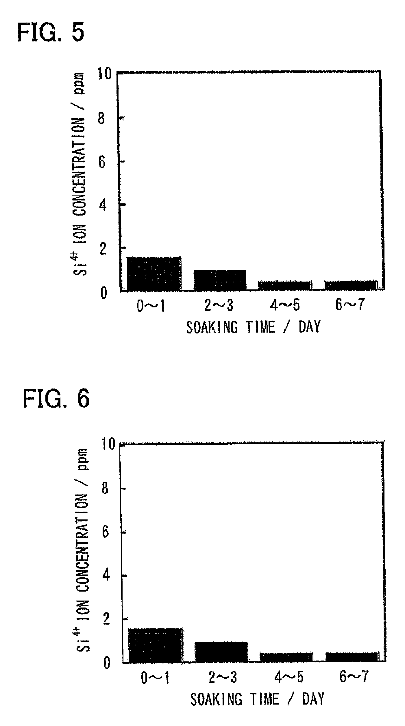
[0058]APTES (1 g) was added to ultrapure water (0.5 g) with stirring to give a solution. The solution was added dropwise to an 8% by weight PLA solution in CHCl3 so as to give an APTES content of 0.015 g and 0.050 g, respectively, followed by stirring. During this procedure, APTES was condensed to give a siloxane. To the resulting mixtures were added 1.5 g of ethanol and 1 g of ultrapure water to give spinning solutions. These spinning solutions were subjected to electrospinning and thereby yielded three-dimensional structures each including a fibrous substance containing a biodegradable resin as a principal component and containing or bearing a siloxane (hereinafter these steric structures are referred to as Si-PLA15 and Si-PLA50, respectively).

[0059]FIG. 3 depicts the appearance of the resulting three-dimensional structure (Si-PLA15). FIG. 4 shows a scanning electron micrograph (SEM) of this steric structure, demonstrating that the steric structure is a flocculent structure includ...

example 2

[0061]A Si—CaCO3 / PLA three-dimensional structure was prepared by kneading PLA and Si—CaCO3 in a heating kneader at 200° C. for 15 minutes to give a Si—CaCO3 / PLA composite containing 40 percent by weight of Si—CaCO3; mixing 1.67 g of the Si—CaCO3 / PLA composite with 8.33 g of CHCl3 to give a solution; adding 1.5 g of ethanol and 1 g of ultrapure water to the solution to give a spinning solution; and subjecting the spinning solution to electrospinning under the above-mentioned conditions.

[0062]The prepared three-dimensional structure has a flocculent appearance substantially the same as that shown in FIG. 3 and had superior flexibility and elasticity. FIG. 7 is a scanning electron micrograph (SEM) of the Si—CaCO3 / PLA three-dimensional structure, demonstrating that this steric structure is a structure including fine fibers having diameters of about 0.1 to about 3 μm and spherical calcium carbonate particles having diameters of about 1 μm embedded between the fibers. The fibers have smal...


PUM

PropertyMeasurementUnit
diameteraaaaaaaaaa
densityaaaaaaaaaa
diameteraaaaaaaaaa

Abstract

A fiber wadding for filling bone defects having a flocculent three-dimensional structure is disclosed. The fiber wadding includes a plurality of fibers that contain a biodegradable resin as a principal component and a siloxane. Outside diameter of the plurality of fibers of the wadding is from about 0.05 μm to about 30 μm. Bulk density of the fiber wadding is about 0.005-0.3 g / cm3.

Description

CROSS REFERENCE TO RELATED APPLICATIONS[0001]This application is a continuation-in-part application of U.S. patent application Ser. No. 12 / 707,302, filed on Feb. 17, 2010, which claims the priority of Japanese Patent Application No. 2009-163320, filed on Jul. 10, 2009. The present application claims the priority of these two prior applications and Japanese Patent Application No. 2011-021790, filed on Feb. 3, 2011. The contents of these three prior applications are incorporated herein by reference in their entirties.FIELD OF THE INVENTION[0002]The present invention relates to bioactive materials which are useful as bone-repairing materials for filling bone defects and may be used in the fields, such as oral or maxillofacial surgery and orthopedic surgery. More specifically, the present invention relates to a fiber wadding for filling bone defects. The fiber wadding has a three-dimensional structure and comprises a bioresorbable-biodegradable resin.BACKGROUND OF THE INVENTION[0003]Som...

Claims


Application Information

Patent Timeline
Patent Type & Authority Patents(United States)
IPC IPC(8): A61F2/28C08K9/02A61L27/32A61L27/46C08L67/04A61F2/30A61F2/44A61L27/18A61L27/26A61L27/44
CPCA61F2/28A61L27/58A61L27/18A61L27/26A61L27/32A61L27/446A61L27/54A61L24/046A61L24/02A61K33/10A61K9/70A61K31/755A61K31/80C08L67/04C08L83/04A61F2002/4495A61L2430/02A61F2/3094Y10T442/2033
Inventor KASUGA, TOSHIHIROOBATA, AKIKOFUJIKURA, KIEOTA, YOSHIOYAO, XIANFENG
Owner NAGOYA INSTITUTE OF TECHNOLOGY
Learn More