
Image pickup apparatus, image pickup element, and method for correcting sensitivity difference

a pickup apparatus and sensitivity difference technology, applied in the field of image pickup apparatus, image pickup element, and method for correcting sensitivity difference, can solve the problems of deterioration in image reproducibility, difficult to reliably correct sensitivity differences, and difficulty in ensuring sufficient color reproducibility, so as to achieve low load, ensure color reproducibility, and high precision

Inactive Publication Date: 2014-08-19
FUJIFILM CORP
View PDF14 Cites 11 Cited by
  • Summary
  • Abstract
  • Description
  • Claims
  • Application Information

AI Technical Summary

Benefits of technology

[0017]The presently disclosed subject matter has been made in view of such circumstances, and it is an object of the presently disclosed subject matter to provide an image pickup apparatus, an image pickup element, and a method for correcting a sensitivity difference, which are capable of obtaining a high-definition image by correcting sensitivity differences, which are attributed to a configuration where a plurality of pixels share a specific circuit element, with a low load and at high precision and by realizing sufficient color reproducibility.
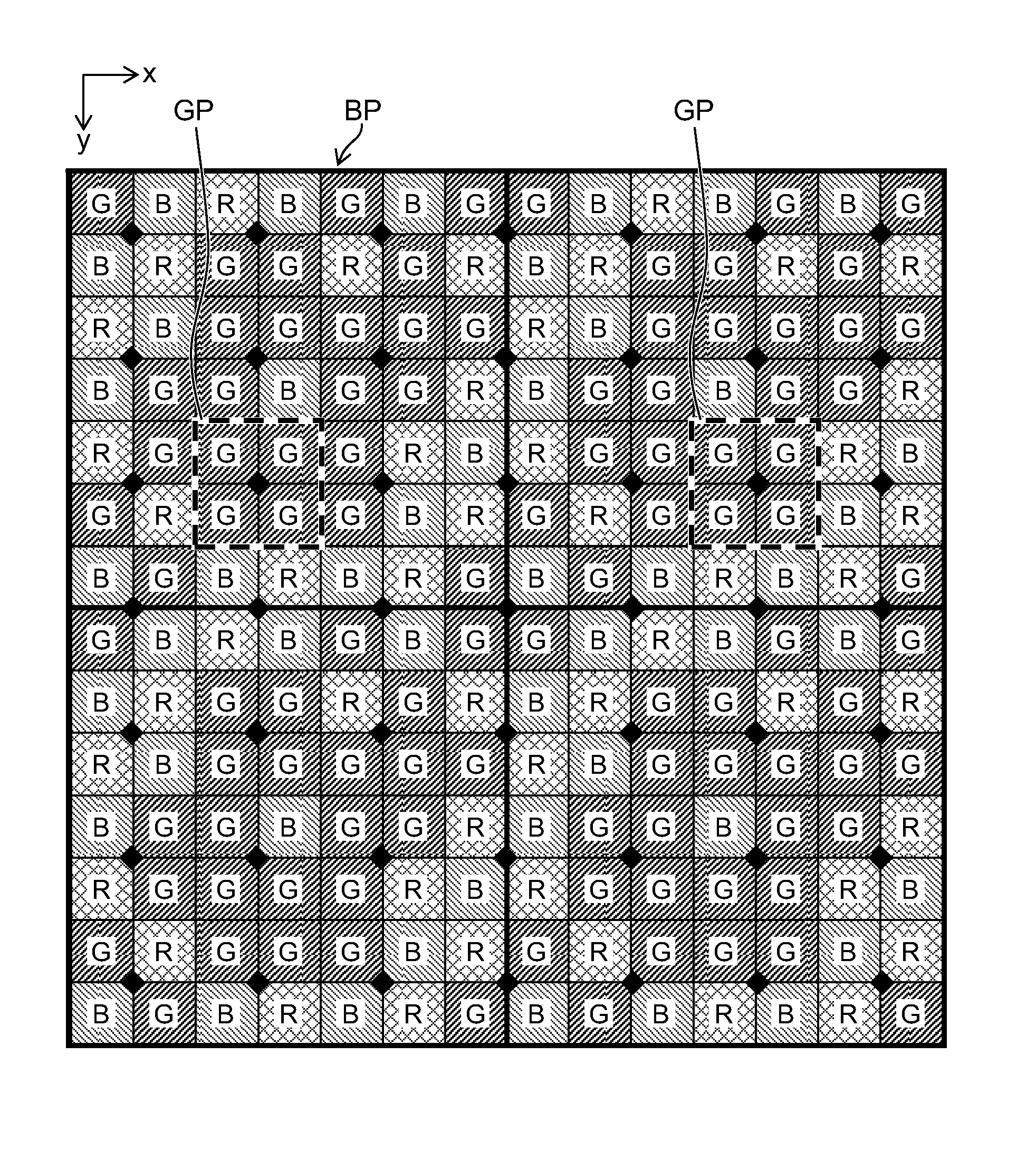
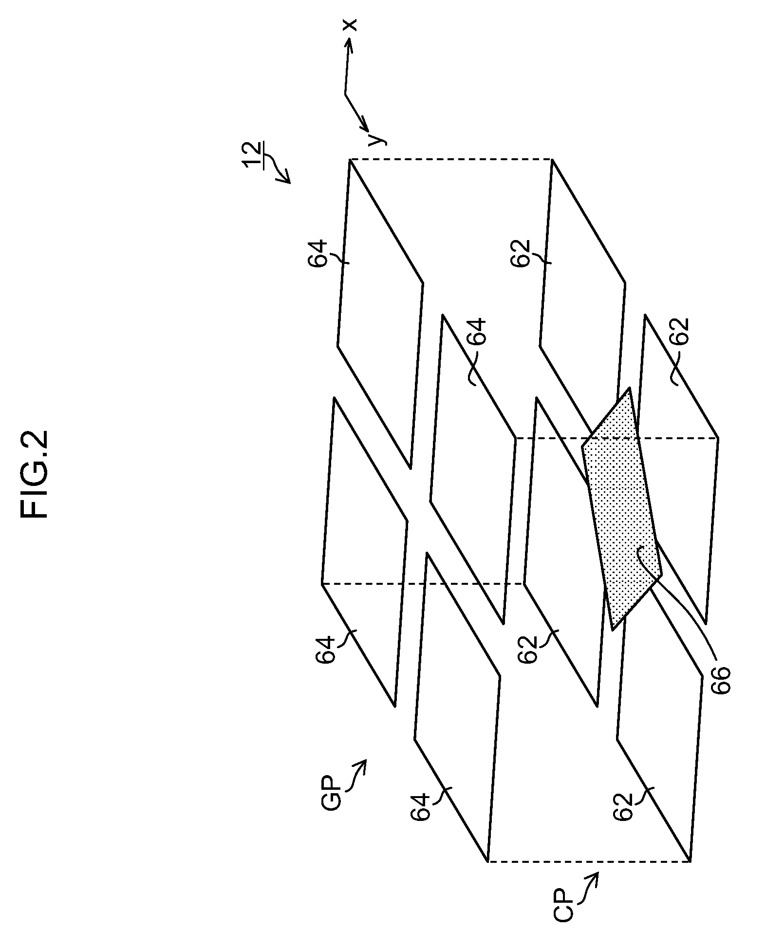
[0019]More specifically, the image pickup element is included, the image pickup element being formed from the basic array patterns of color filters being repeatedly arranged in the horizontal direction and the vertical direction, each of the basic array patterns of the color filters including at least one same-color square array pattern which is made of 2×2 color filters matched with the 2×2 pixels of the sharing configuration pattern that share a specific circuit element, the 2×2 color filters having a same color. The storage means and the sensitivity difference correction means are further included, the storage means being configured to store the information calculated from output values of the 2×2 pixels corresponding to the same-color square array pattern among I×J pixels corresponding to the basic array pattern, and the sensitivity difference correction means being configured to correct the sensitivity differences between all the pixels of the image pickup element with use of the information on the sensitivity of the 2×2 pixels corresponding to the same-color square array pattern stored in the storage means. Accordingly, it becomes possible to correct sensitivity differences, which are attributed to the configuration where a plurality of pixels shares a specific circuit element, by low load processing to secure color reproducibility, so that a high-definition image can be obtained.
[0026]In one aspect, the detection means calculates characteristic information by averaging output values of respective pixels (k-th pixels) in the 2×2 pixels corresponding to the same-color square array pattern in a plurality of pixels (k-th pixel group) which are in a same position with respect to the specific circuit element, the detection means dividing a whole region corresponding to the picked-up image of the image pickup element and averaging the output values of the pixels in each of division areas. That since the sensitivity is detected by averaging the output values of the pixels in each of the division areas, it becomes possible to cope with surface shading generated depending on a circuit layout of the image pickup element.
[0029]According to the presently disclosed subject matter, it becomes possible to obtain a high-definition image by correcting sensitivity differences, which are attributed to the configuration where a plurality of pixels share a specific circuit element, with a low load and at high precision and by realizing sufficient color reproducibility.

Problems solved by technology

However, in the configuration where color filters 94 were arranged on pixels 92 according to the Bayer array and four pixels 92 shared one amplifier 96 as illustrated in FIG. 18, a problem of deterioration in image reproducibility due to the amplifier-sharing configuration and a problem of deterioration in image reproducibility due to the color filter array being the Bayer array coexisted.
This made it difficult to reliably correct sensitivity differences and to secure sufficient color reproducibility.
In short, the pixels 92 different in position with respect to the amplifier 96 have varied sensitivity due to difference in layout of the substrate and the like, which caused a problem of an adverse effect being exerted on the image reproducibility.

Method used


Image

  • Image pickup apparatus, image pickup element, and method for correcting sensitivity difference
  • Image pickup apparatus, image pickup element, and method for correcting sensitivity difference
  • Image pickup apparatus, image pickup element, and method for correcting sensitivity difference

Examples


Embodiment Construction

[0050]Hereinafter, embodiments of the presently disclosed subject matter are described in detail with reference to the accompanying drawings.

[Overall Configuration of Image Pickup Apparatus]

[0051]FIG. 1 is a block diagram illustrating an overall configuration of one example of an image pickup apparatus according to the presently disclosed subject matter. Herein, the image pickup apparatus is not limited to a single camera unit, but may include various kinds of information devices and electronic equipment, such as camera-equipped mobile phones, camera-equipped smartphones, camera-equipped tablet computers, and camera-equipped music players.

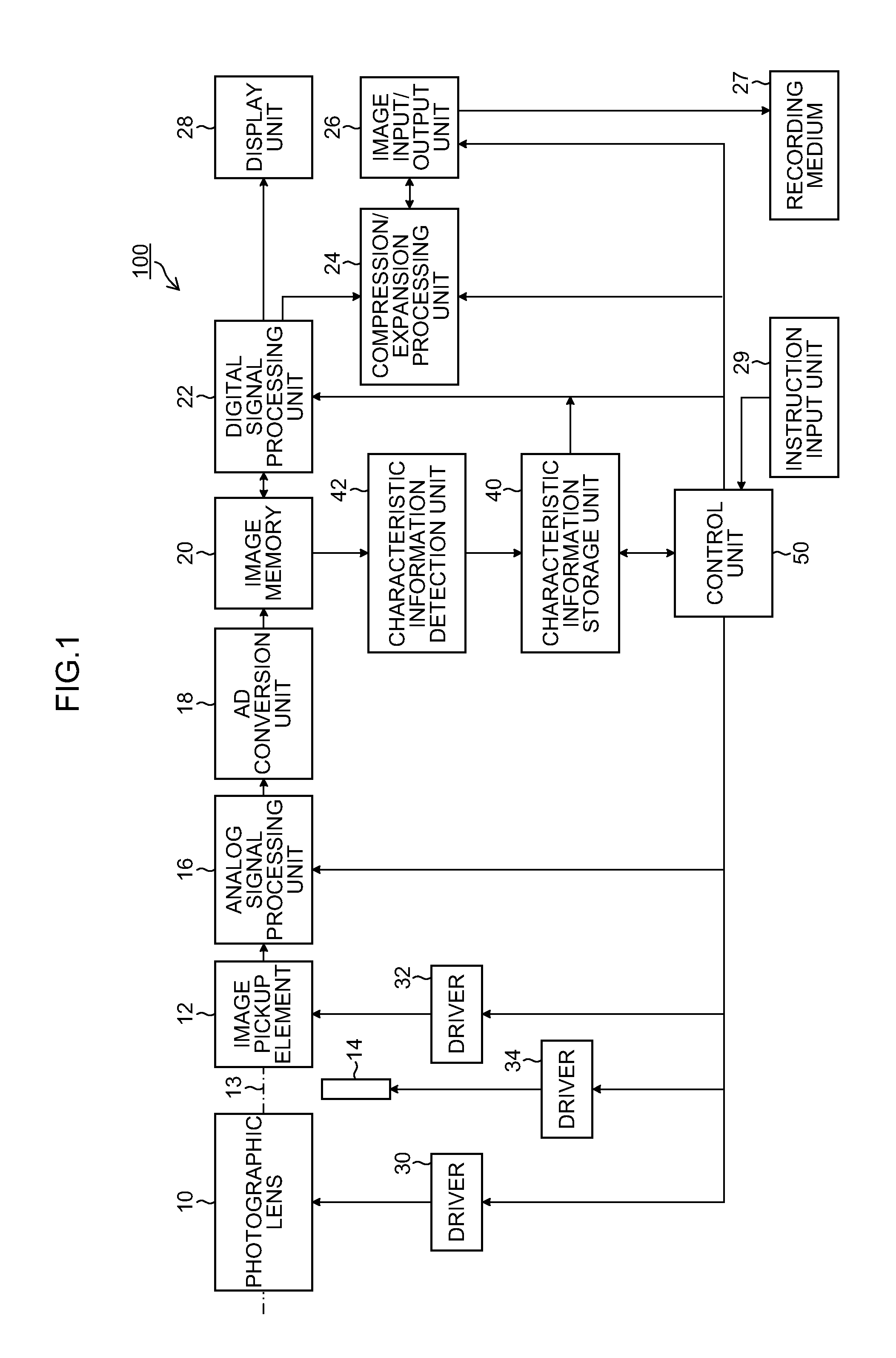
[0052]An image pickup apparatus 100 includes a photographic lens 10 configured to form an image of incident object light as an object image, an image pickup element 12 configured to pick up an object image formed with the photographic lens 10, a mechanical shutter 14 (opening / closing means) configured to open and close an optical path 13 of the obj...


PUM


Abstract

In an image pickup element, basic array patterns are repeatedly arranged in a horizontal direction and a vertical direction, each of the basic array patterns being made of I×J color filters, the color filters of each of three or more colors being arrayed in a mixed state, an arrangement cycle (I×J) of a basic array pattern is different from an arrangement cycle (2×2) of a sharing configuration pattern, the basic array pattern includes at least one same-color square array pattern which is made of 2×2 color filters of a same color respectively arranged on the 2×2 pixels of the sharing configuration pattern, a characteristic information storage unit stores information on sensitivity calculated from output values of the 2×2 pixels, and a control unit and a digital signal processing unit correct a sensitivity difference between all the pixels of the image pickup element with use of the information on the sensitivity.

Description

[0001]This application is a continuation of PCT / JP2012 / 065832 filed on Jun. 21, 2012, which claims priority under 35 U.S.C. 119(a) to Patent Application No. 2011-155135 filed in Japan on Jul. 13, 2011, all which are hereby expressly incorporated by reference into the present application.BACKGROUND OF THE INVENTION[0002]1. Field of the Invention[0003]The presently disclosed subject matter relates to an image pickup apparatus and an image pickup element configured to include a plurality of pixels that share a specific circuit element, and a method for correcting a sensitivity difference.[0004]2. Description of the Related Art[0005]An image pickup element made of a CMOS (complementary metal oxide semiconductor) is low in power consumption and is used for various kinds of portable image pickup apparatuses such as digital cameras and mobile phones.[0006]In the CMOS image pickup element, a technology that a plurality of pixels share one amplifier is widely used as a technology for reducin...

Claims


Application Information

Patent Timeline
Patent Type & Authority Patents(United States)
IPC IPC(8): H04N9/083H04N5/335
CPCH04N5/361H04N9/07H04N5/37457H04N9/045H04N25/63H04N25/778H04N23/84H04N23/12H04N25/134
Inventor KAWAI, TOMOYUKI
Owner FUJIFILM CORP
Learn More