
Anti-back-out fastener for applications under vibration

a technology of anti-back-out and vibration, which is applied in the direction of fastening means, pins, washers, etc., can solve the problems of elongation of studs or bolts, inconvenient use of threads, and thin wall construction, etc., and achieves the effect of greater inclination

Active Publication Date: 2014-08-19
DISC LOCK LLC
View PDF16 Cites 23 Cited by
  • Summary
  • Abstract
  • Description
  • Claims
  • Application Information

AI Technical Summary

Benefits of technology

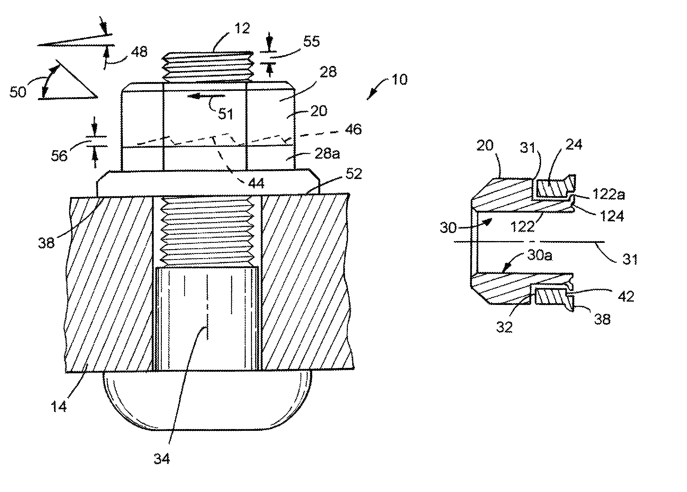
[0012]A fastener is disclosed for use in a high vibration application wherein the fastener is engaged to a blind hole. The fastener includes a lock washer including wedge locking action fastening features and a head of the fastener including mating wedge locking action fastening features. The wedge locking action fastening features include a greater inclination than a pitch angle of the fastener such that the fastener is prevented from backing out.

Problems solved by technology

Vibration or shock will cause the stud or bolt to elongate.
One shortcoming of the prior art and commercially available self tightening fasteners is that the stacked nut and washer have a combined height which presents a relatively large profile preventing these fasteners from being used in certain situations, e.g. where there is a small fastener clearance dimension.
This thin wall construction, however, is not conducive to threading.
While my prior fastener was adequate for some applications, the relatively high profile prevented its use in other applications.
Vibration of the objects tends to loosen a screw in a blind hole.
Screws utilized in industrial or heavy machinery applications can be exposed to heavy vibration, and loose screws can cause malfunctions or failure in the machinery.
Such a method can be labor intensive and potentially hazardous, depending upon a location of the screws to be checked.
However, one having skill in the art will appreciate that such a remedy is likely to increase the time that the screw takes to back-out rather than permanently stop the screw from backing out.

Method used


Image

  • Anti-back-out fastener for applications under vibration
  • Anti-back-out fastener for applications under vibration
  • Anti-back-out fastener for applications under vibration

Examples


Embodiment Construction

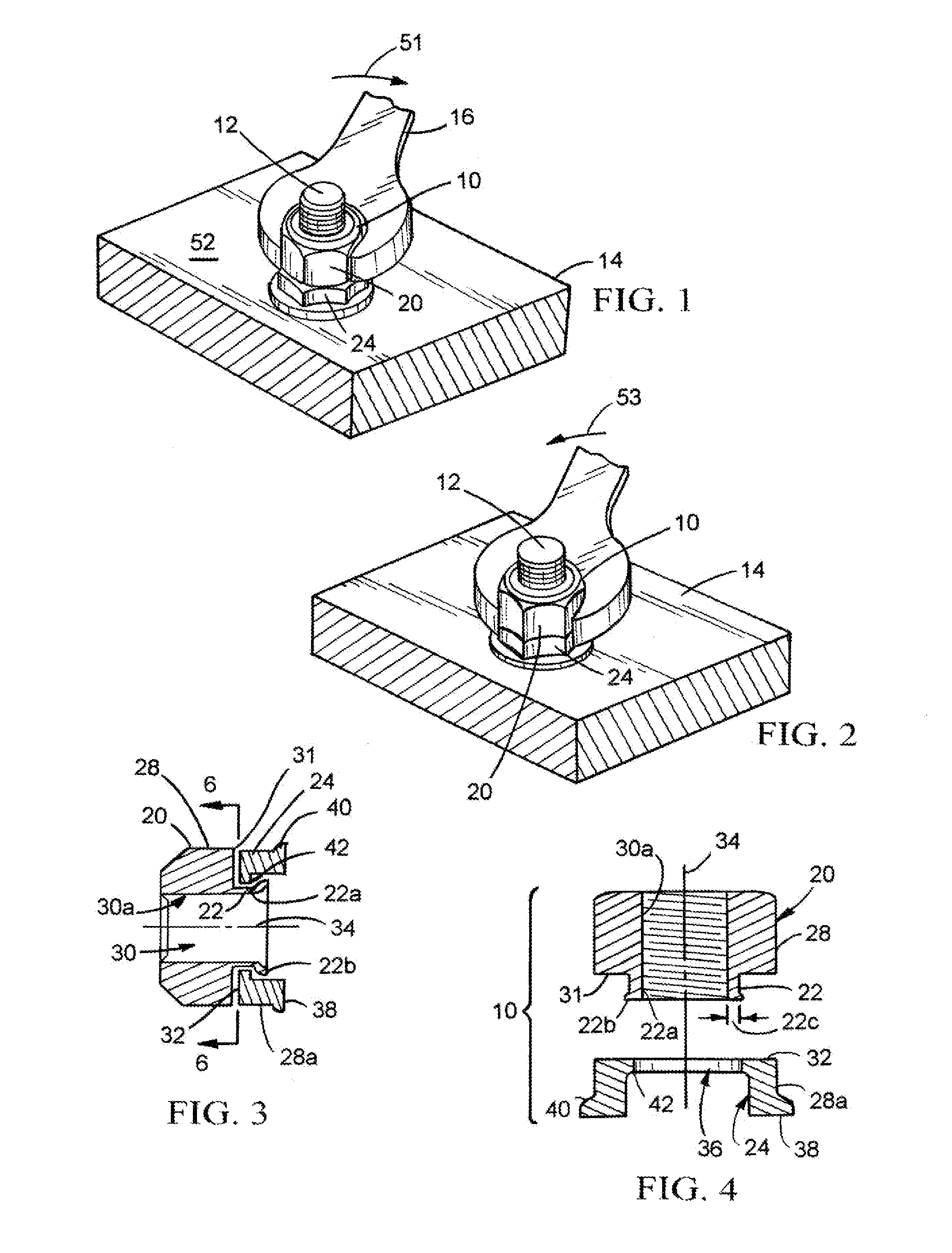
[0054]Referring now to the drawings, wherein the showings are for the purpose of illustrating certain exemplary embodiments only and not for the purpose of limiting the same, a cam locking fastener 10 is mounted on a threaded stud 12 which is secured to a workpiece 14. A wrench 16 is used for tightening the fastener 10 on the stud in the clockwise direction to apply a load on the workpiece. The wrench is rotated in the opposite direction for loosening the fastener means and releasing the load on the workpiece.

[0055]Fastener 10 comprises a nut 20 having a tubular skirt 22, and a locking. Referring to FIGS. 1, 2, 5 and 8, the nut has a six-sided conventional hexagonal external configuration 28 engaged with a conventional nut-receiving opening in wrench 16. Nut 20 has a through opening 30 having an internal threaded surface 30a meshed with the continuous helical thread on stud 12 by application of a wrench 16 to flat multi-sided external surfaces 28. In the preferred embodiment, fasten...


PUM


Abstract

A fastener is disclosed for use in a high vibration application wherein the fastener is engaged to a blind hole. The fastener includes a lock washer including wedge locking action fastening features and a head of the fastener including mating wedge locking action fastening features. The wedge locking action fastening features include a greater inclination than a pitch angle of the fastener such that the fastener is prevented from backing out.

Description

CROSS-REFERENCE TO RELATED APPLICATION[0001]This disclosure is a continuation-in-part of U.S. patent application Ser. No. 12 / 541,903 filed on Aug. 14, 2009 which claims the benefit of U.S. Provisional Application No. 61 / 088,962 filed on Aug. 14, 2008 and claims the benefit of U.S. Provisional Application No. 61 / 694,493 filed on Aug. 29, 2012 which is hereby incorporated by reference.TECHNICAL FIELD[0002]This disclosure is related to threaded mechanical fasteners and more particularly to locking nuts, wheelnuts, and self-tightening nuts including anti-back-out features.BACKGROUND OF THE DISCLOSURE[0003]A variety of cam locking or “self-tightening” fasteners have been disclosed in the prior art. Such fasteners accommodate a workpiece exposed to vibration. Some prior art devices may be found in U.S. Pat. No. 3,263,727 which issued Aug. 2, 1966 to Arthur B. Herpolsheimer; U.S. Pat. No. 3,417,802 which issued Dec. 24, 1968 to Carl O. Oldenkott; and Canadian Pat. No. 1,320364 which issued...

Claims


Application Information

Patent Timeline
Patent Type & Authority Patents(United States)
IPC IPC(8): F16B39/24F16B39/282F16B41/00
CPCF16B39/282F16B39/24F16B41/002
Inventor MCKINLAY, ALISTAIR
Owner DISC LOCK LLC
Learn More