
Method for quality control during ultrasonic

a technology of quality control and ultrasonic, which is applied in the direction of gas flame welding apparatus, non-electric welding apparatus, auxilary devices, etc., can solve the problems of poor bonded connection deformation and current profile, unsuitable for detecting with certainty a bond of inferior quality, and methods that do not achieve the aim

Active Publication Date: 2014-07-22
HESSE
View PDF39 Cites 5 Cited by
  • Summary
  • Abstract
  • Description
  • Claims
  • Application Information

AI Technical Summary

Benefits of technology

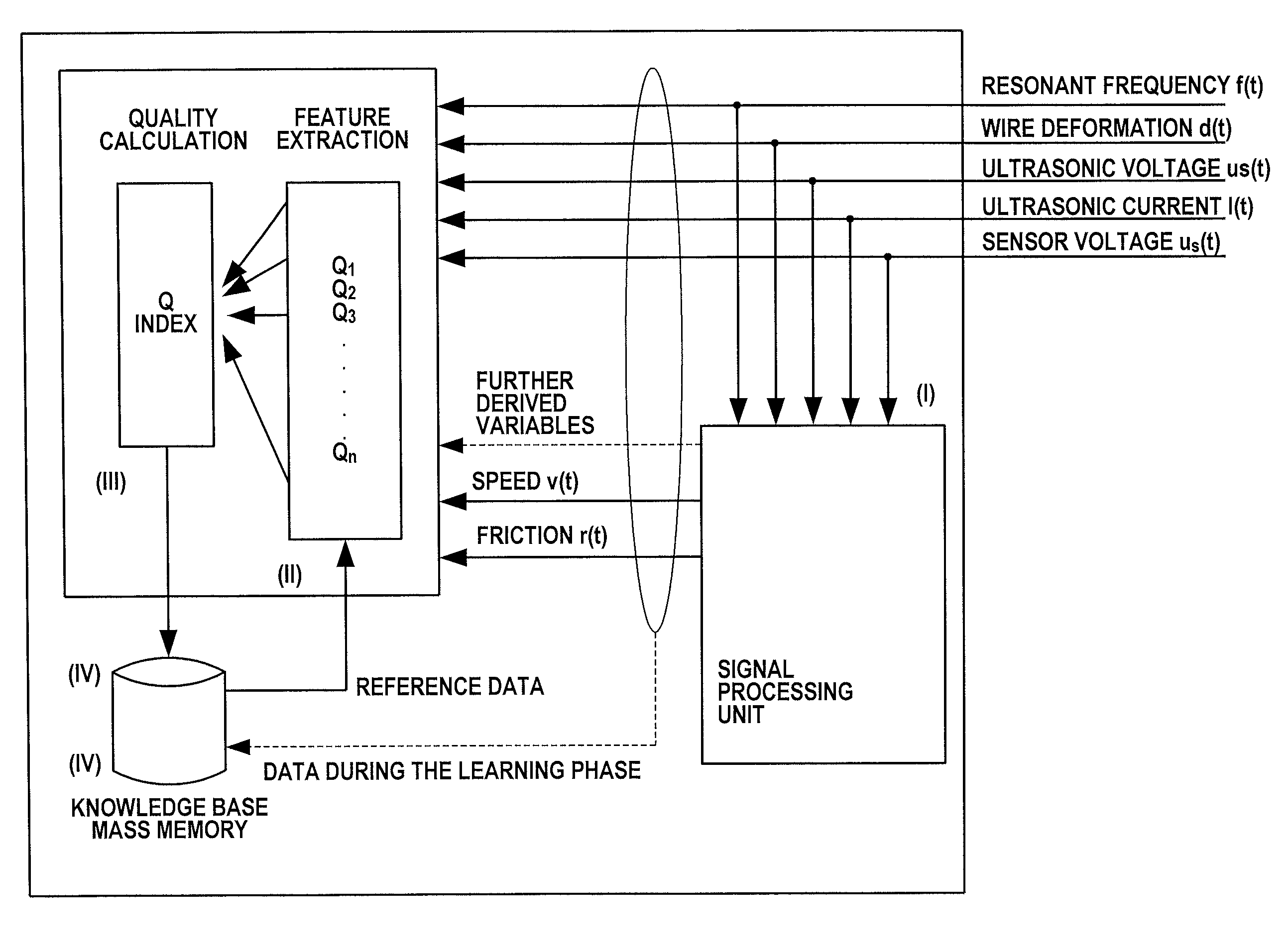
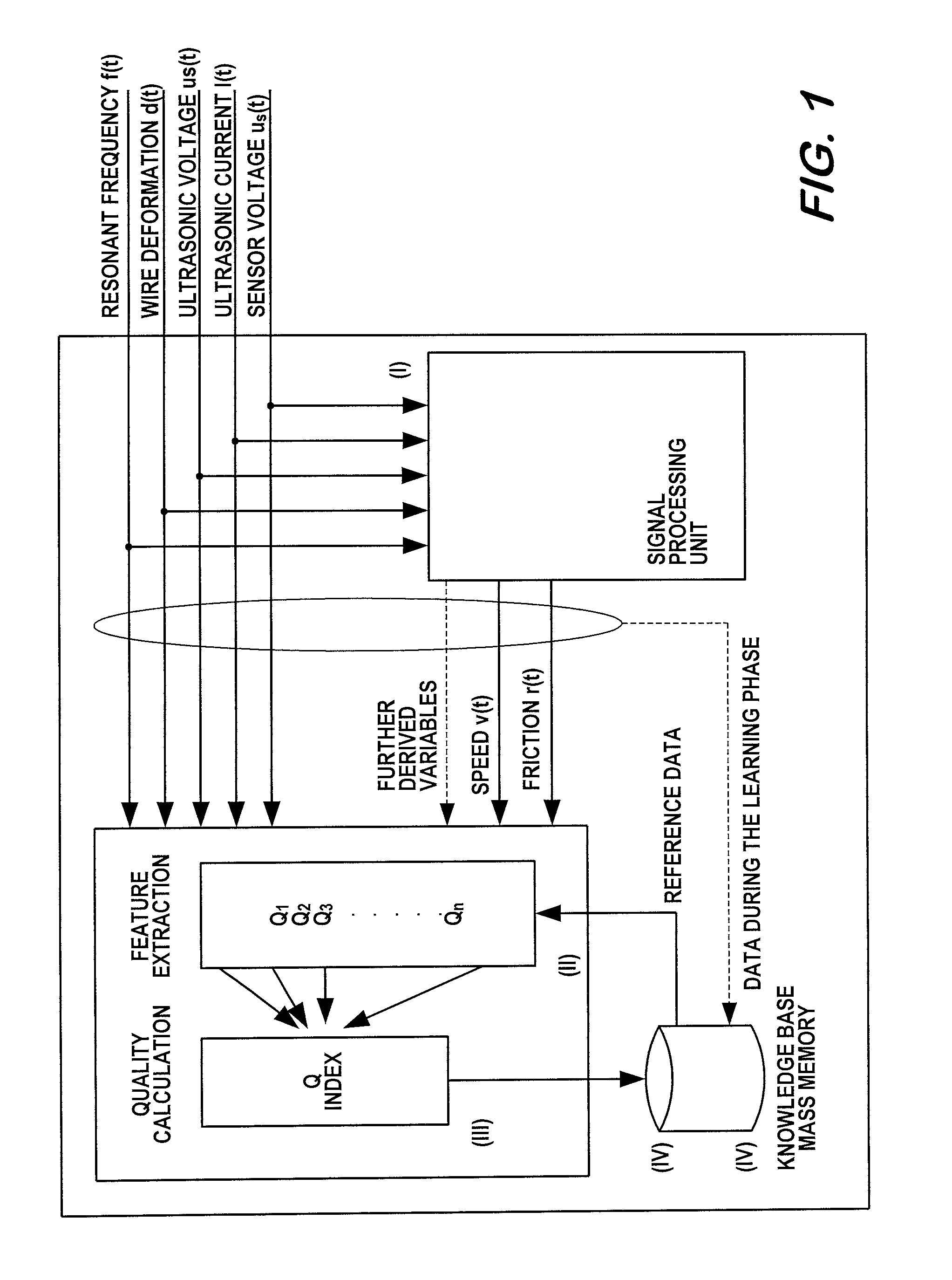
[0021]Alternatively or in combination, a quality value characterizing the quality of a bonding operation or a bonded connection may be determined from the friction value / time profile and a setpoint friction value / time profile that is predetermined or determined and stored beforehand by means of a computer in a learning phase, preferably according to or by analogy with features explained below. For example, the setpoint profile of the derived friction may also be represented as a vector, and its elements may be compared step by step with temporally associated elements of the actual vector. For example, a deviation vector may be formed from the respective differences. Generation of setpoint value profiles of measured variables and / or derived variables in a preceding learning phase, is also referenced in the description below. The quality value may also be used for controlling and / or regulating subsequent bonding operations, preferably in the course of influencing manipulated variables such as the bonding force, ultrasonic power, bonding time and / or ultrasonic frequency. The quality value may also be used for influencing manipulated variables of the bonding process, such as in particular the bonding force, ultrasonic power, bonding time and / or ultrasonic frequency in the course of controlling or regulating and / or for the emission of warning signals when critical values are reached. It has been found that the profiles of the tool speed in the direction of oscillation occurring during individual bonding operations and profiles derived therefrom (in particular the derived friction) can, depending on the bonding conditions, make it possible to provide a more reliable determination of the quality of a bonding operation compared to conventional evaluation parameters (in particular, wire deformation). The method according to the invention therefore makes more precise monitoring of the quality of a bond possible in comparison with the prior art, and if need be (for example if the bonding conditions change), improved influencing of manipulated variables to obtain consistently high quality bonds. In particular, a regime of controlling and / or regulating bonding processes may integrate a setpoint / actual comparison of the derived friction, with the further possibility that additional parameters could also be taken into consideration.
[0034]It is preferably provided that, in the calculation of the quality index Q, at least some of the deviation profiles are weighted individually, and may be weighted independently of one another, in particular according to information previously stored in a memory. The accuracy of the quality assessment can also be increased by variably weighting one or more deviation profiles temporally or in their variation (i.e. with respect to the various elements of the deviation vector) during the calculation.
[0066]The invention described above makes it possible to classify potential errors during bonding processes, to automatically allocate them to error classes and to name bonding errors in an automated manner. To this extent, the invention may include generating correction variables in real time in dependence on input textures in the feature extraction and providing feedback to the process controlling system. The invention may also include generating correction variables in the quality calculation in the form of a trend analysis and providing feedback to the process controlling system. A further possible application is monitoring user interventions and checking over maintenance work. The invention also makes it possible to transform an error vector to a scalar quality variable.

Problems solved by technology

A weakness of this method is that even poor bonded connections may exhibit such deformation and current profiles.
Consequently, the set procedure specified is necessary, but in no way sufficient for determining the quality of a bond, and is therefore unsuitable for detecting with certainty a bond of inferior quality.
These methods do not achieve the aim either, since the measured variables used do not correlate sufficiently with the physical processes taking place in the connecting zone.
The described methods that have so far become known are therefore not suitable for acquiring the data essential for assessing the quality of a connection and processing them correspondingly.
To this extent, these methods cannot satisfy the requirements for quality monitoring in fully automatic bonders.

Method used


Image

  • Method for quality control during ultrasonic
  • Method for quality control during ultrasonic
  • Method for quality control during ultrasonic

Examples


second embodiment

[0086]Optionally, feature vectors (Q1 . . . Qn) or error vectors may be categorized with regard to their associated error in a further step. FIG. 5 shows the preferred basic construction of a system suitable for this. The calculation of the quality values takes place in principle as described in the A further module, which allocates the result to a result class, and to this extent can specify causes of errors, is provided (cf. FIG. 5, Block 1.3.3).

[0087]The raw data from the signal preprocessing and the ultrasonic generator are not only used for feature extraction (FIG. 5, 1.3.1), but are likewise passed on to a monitoring unit not operating in real time. The monitoring unit likewise receives the result of the quality calculation and of the error classifier (FIGS. 5, 1.3.2 and 1.3.3). The feature extraction, the quality calculation and the error classification each have a further input, through which the results of the monitoring unit are fed back into the calculation of the qualit...

first embodiment

[0092]In Block 1 of FIGS. 7 and 8, essential components of an ultrasonic generator are represented, suitable for setting electrical resonance. The comparators 1 and 2 respectively convert the sinusoidal signals for current and voltage into square-wave signals, the zero crossing of which in each case coincides with the zero crossings of the sinusoidal oscillations. Then the phase comparator is used to determine the phase difference between the current and the voltage of the ultrasonic signal. The actual phase value determined in this way is fed to the downstream phase regulator (PID controller) as an input variable. The setpoint phase value for resonance is zero. The output variable of the regulator is the input variable of the DDS (Direct Digital Synthesizer), this variable θcorr is the phase increment on the basis of which the frequency of the output signal of the DDS is set. This signal is then amplified by means of a power amplifier and fed to the ultrasonic transducer. The regu...


PUM

PropertyMeasurementUnit
probability density functionaaaaaaaaaa
timeaaaaaaaaaa
electrical signalsaaaaaaaaaa

Abstract

A method for quality control during ultrasonic bonding, in which a transducer bonding tool unit and an ultrasonic generator are used and in which, during the bonding, one or more sensors are used to sense measurement signals for one or more parameters, which can vary during the bonding, for assessing the bond quality and / or for influencing the bonding, and which proposes that, during the bonding, at least one speed profile measurement signal representing the time / speed profile of the tip of the ultrasonic tool in the direction of oscillation thereof be sensed. The invention also relates to a bonding apparatus which is suitable for carrying out the method. Furthermore, the invention relates to other quality control methods for ultrasonic bonding and to bonding apparatuses which are suitable for carrying out these methods.

Description

CROSS-REFERENCE TO RELATED APPLICATIONS[0001]The present application is a continuation of pending International patent application PCT / EP2008 / 065101 filed on Nov. 7, 2008, which designates the United States and claims priority from German patent application number 10 2007 054 626.4 filed on Nov. 12, 2007, the content of which is incorporated herein by reference.FIELD OF THE INVENTION[0002]The invention relates to methods for the production and quality control of bonded connections, in particular ultrasound wire bonded connections, and to components suitable for carrying out these methods as well as to bonding apparatuses equipped with components of this kind, in particular wire bonders. The invention also relates in particular to wedge-wedge bonding. The overall aim of the invention is improved productivity and improved quality control compared to conventional techniques.BACKGROUND OF THE INVENTION[0003]Wedge-wedge bonding is a generally recognized and reliable technique for establi...

Claims


Application Information

Patent Timeline
Patent Type & Authority Patents(United States)
IPC IPC(8): B23K1/06B23K31/00B23K20/00
CPCH01L22/00B23K20/005H01L2924/0002B23K31/125H01L2924/00
Inventor HESSE, HANS-JUERGENBROEKELMANN, MICHAELHAGENKOETTER, SEBASTIAN
Owner HESSE
Learn More