Refrigerant compressor
a compressor and refrigerant technology, applied in the direction of positive displacement liquid engines, piston pumps, liquid fuel engines, etc., can solve the problems of many unsolved technical problems, reduce the performance of heat exchangers, and increase the amount of stored oil inside sealed vessels, so as to suppress heat exchanger performance and reduce reliability. , the effect of reducing the amount of stored oil inside the sealed vessel
- Summary
- Abstract
- Description
- Claims
- Application Information
AI Technical Summary
Benefits of technology
Problems solved by technology
Method used
Image
Examples
embodiment 1
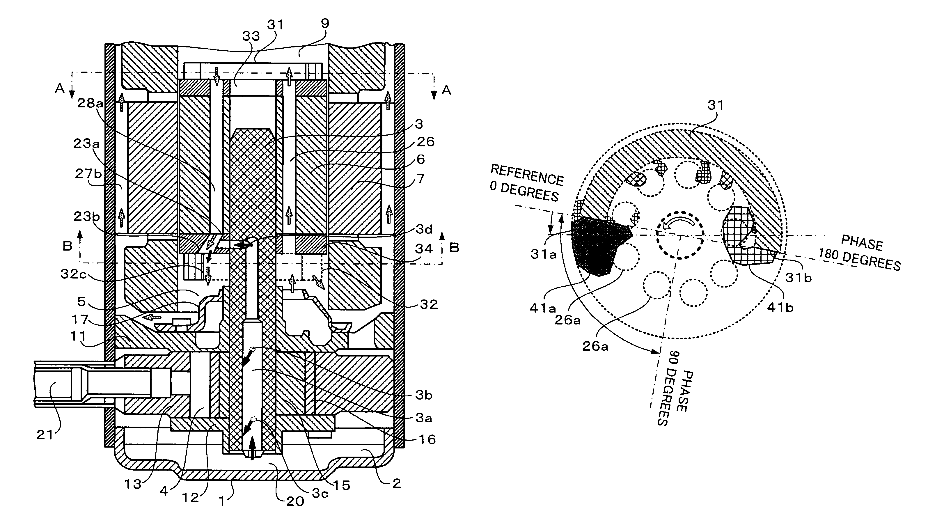
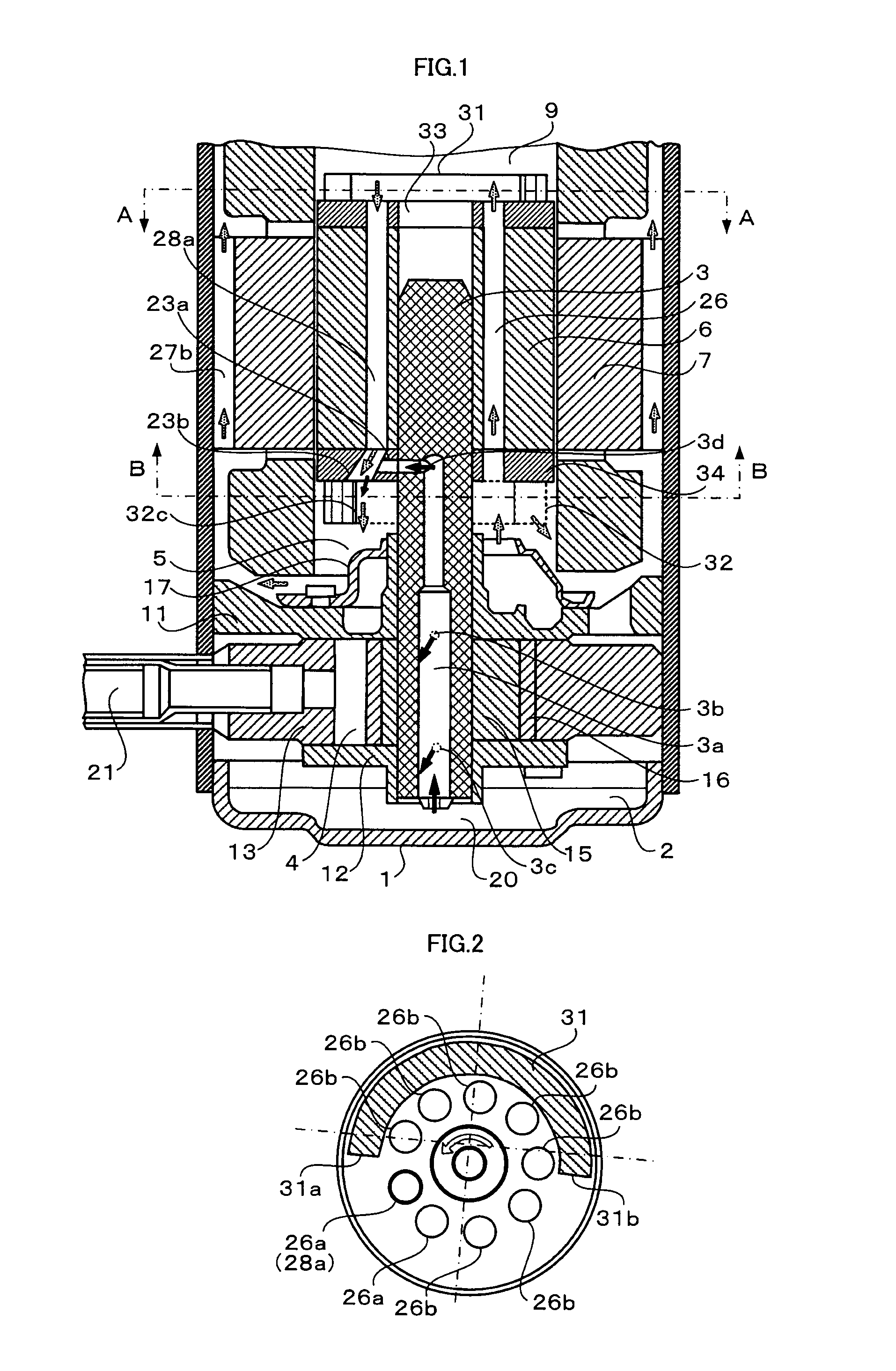
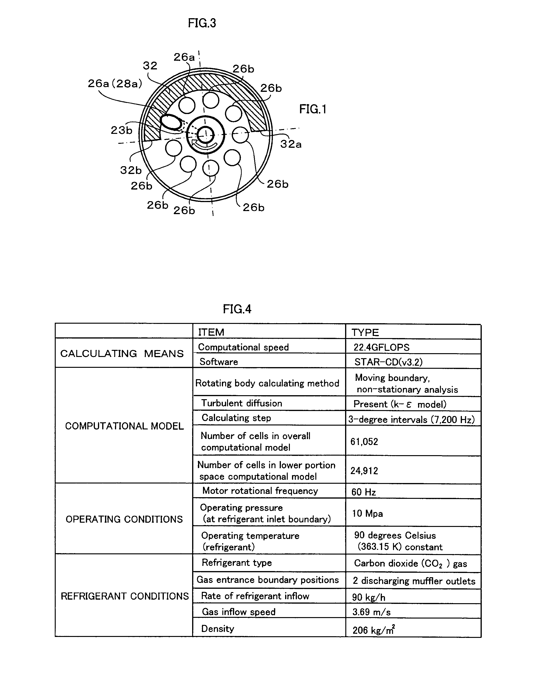
[0029]FIG. 1 is a longitudinal cross section that shows a construction of a rotary compressor according to Embodiment 1 of the present invention. FIG. 2 is a schematic layout of lateral cross section A in FIG. 1. FIG. 3 is a schematic layout of lateral cross section B in FIG. 1.
[0030]First, basic construction and operation of a rotary compressor that functions as a refrigerant compressor according to Embodiment 1 of the present invention will be explained. Moreover, in FIG. 1, solid black arrows indicate oil flow, and stippled arrows indicate refrigerant gas flow.
[0031]As shown in FIG. 1, a rotary compressor according to Embodiment 1 of the present invention includes: an electric motor that has a stator 7 and a rotor 6; and a compressing mechanism to which torque from the electric motor is transmitted by the crank shaft 3, and in which refrigerant gas is compressed inside a cylinder chamber 4.
[0032]The compressing mechanism includes: an upper bearing member 11; a lower bearing membe...
embodiment 2
[0055]FIG. 7 is a longitudinal cross section that shows a construction of a rotary compressor according to Embodiment 2 of the present invention. FIG. 8 is a schematic layout of lateral cross section A in FIG. 7. FIG. 9 is a schematic layout of lateral cross section B in FIG. 7.
[0056]In a rotary compressor according to Embodiment 2 of the present invention, an oil separating plate 35 is added to the rotary compressor according to Embodiment 1 of the present invention, and a rotor 6B, an upper counterweight 31B, a lower counterweight 32B, a rotor upper portion fixed plate 33B, and a rotor lower portion fixed plate 34B are different, and because other portions are similar, identical numbering will be given to similar portions and explanation thereof will be omitted.
[0057]A ring-shaped oil separating plate 35 is fitted over an upper end portion of the crank shaft 3 so as to be tightly fitted, and is held so as to be separated from the upper ends of the rotor vents 26 of the upper count...
embodiment 3
[0070]FIG. 10 is a longitudinal cross section that shows a construction of a scroll compressor according to Embodiment 3 of the present invention. FIG. 11 is a schematic layout of lateral cross section A in FIG. 10. FIG. 12 is a perspective that shows a rotor upper portion of the scroll compressor according to Embodiment 3 of the present invention.
[0071]A scroll compressor according to Embodiment 3 of the present invention includes a scroll compressing mechanism and an electric motor, and because the scroll compressor is conventional, configuration thereof will be explained simply. The electric motor differs in that oil return flow channels have been added, and because other portions thereof are conventional, configuration thereof will be explained simply.
[0072]The scroll compressing mechanism includes: a fixed scroll 51; a crank shaft 3 that is supported rotatably by a main bearing 54 and an auxiliary bearing 55; and an orbiting scroll 52 that is fitted over and driven by a first e...
PUM
 Abstract
Description
Claims
Application Information
 - R&D
- Intellectual Property
- Life Sciences
- Materials
- Tech Scout
- Unparalleled Data Quality
- Higher Quality Content
- 60% Fewer Hallucinations
Browse by: Latest US Patents, China's latest patents, Technical Efficacy Thesaurus, Application Domain, Technology Topic, Popular Technical Reports.
© 2025 PatSnap. All rights reserved.Legal|Privacy policy|Modern Slavery Act Transparency Statement|Sitemap|About US| Contact US: help@patsnap.com


