
Camera Module

a technology of camera module and camera body, applied in the field of camera module, can solve the problems of affecting the operation of electronic devices, affecting the safety of users, so as to reduce manufacturing costs, improve reliability against drop, and reduce weight

Active Publication Date: 2014-11-20
LG INNOTEK CO LTD
View PDF6 Cites 12 Cited by
  • Summary
  • Abstract
  • Description
  • Claims
  • Application Information

AI Technical Summary

Benefits of technology

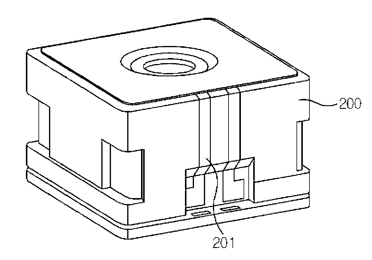
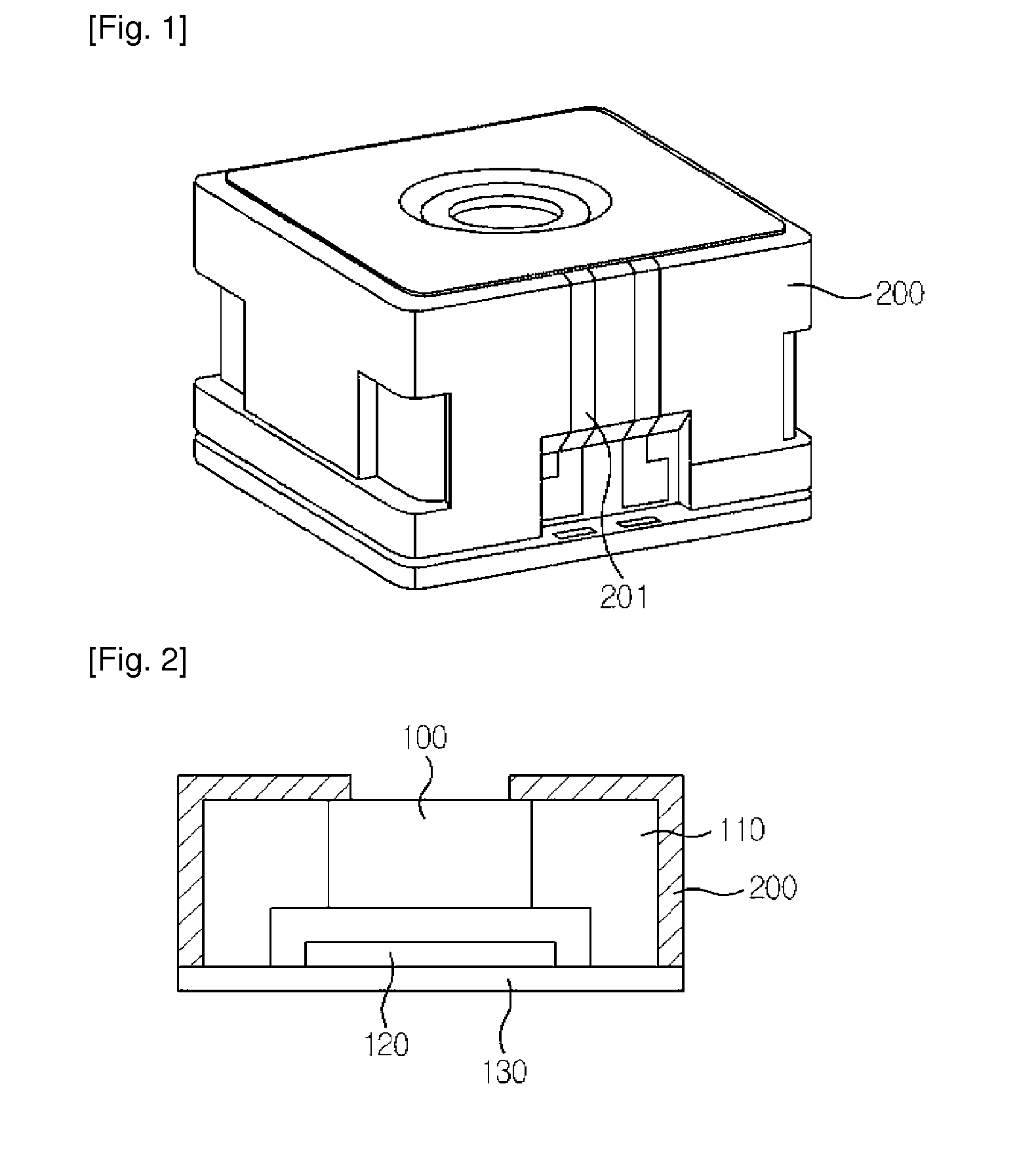
The present invention is a camera module that has a metalized housing to shield against EMI, an electrode line along the housing shape, and a simplified wiring process. This eliminates the need for additional parts, reduces manufacturing costs, improves reliability against drop, and allows for a larger lens to be mounted. Additionally, the electrode line enables embedded parts, reducing the number of parts and simplifying assembly.

Problems solved by technology

Meanwhile, the electromagnetic wave is in an invisible odorless thing like the air we breathe, and hangs around us to disturb other electromagnetic waves called EMI (Electromagnetic Interference) which in turn can interfere with the performance of various sensitive wireless devices nearby, causing industrial damages, and resulting in fatal influences directly or indirectly on human body.
Particularly, a camera module is mounted on portable terminals, notebooks and other electronic devices generating electromagnetic wave, which may result in erroneous operation of the electronic devices, such that multi-angled researches and technical developments are being waged to reduce the electromagnetic wave.

Method used


Image

  • Camera Module
  • Camera Module
  • Camera Module

Examples


Embodiment Construction

[0036]Hereinafter, exemplary embodiments of the present invention will be described in detail with reference to the accompanying drawings.

[0037]In describing the present disclosure, detailed descriptions of constructions or processes known in the art may be omitted to avoid obscuring appreciation of the invention by a person of ordinary skill in the art with unnecessary detail regarding such known constructions and functions. Accordingly, the meaning of specific terms or words used in the specification and claims should not be limited to the literal or commonly employed sense, but should be construed or may be different in accordance with the intention of a user or an operator and customary usages. Therefore, the definition of the specific terms or words should be based on the contents across the specification.

[0038]Furthermore, directional terminology, such as “top,”“bottom,”“front,”“back,” etc., may be used with reference to the orientation of the Figures being described. Because ...


PUM


Abstract

The present invention relates to a camera module, the camera module including a PCB (Printed Circuit Board) mounted with an image sensor, a housing configured to protect the image sensor and mounted therein with camera constituent parts, and plural pieces of lenses mounted on the housing, wherein a surface of the housing is metalized.

Description

TECHNICAL FIELD[0001]The teachings in accordance with exemplary embodiments of this invention relate generally to a camera module.BACKGROUND ART[0002]Generally, an optical device includes a lens transfer device moving a lens to an optical direction, where the lens transfer device uses an actuator such as an electro-magnetic motor or a piezoelectric actuator as a means for generating a power. A cam or a screw is used as a means for transmitting power generated by the actuator.[0003]Thus, the lens transfer device uses the power generated by the actuator to adjust a focus by moving the lens to an optical direction, whereby auto-focusing function is realized.[0004]Especially, in recent times, mobile terminals and PDAs (personal digital assistants) are largely and frequently mounted with a camera module. The camera module may be equipped with an AF (Auto Focusing) function, and a VCM (Voice Coil Motor) is used for auto focusing function, where the VCM performs the auto focusing function ...

Claims


Application Information

Patent Timeline
Patent Type & Authority Applications(United States)
IPC IPC(8): H04N5/225G03B13/36
CPCG03B13/36H04N5/2254G03B17/02G03B2205/0053H04N23/57H04N23/55G03B30/00H04N23/51H04N23/54
Inventor HAN, KWANG JOON
Owner LG INNOTEK CO LTD
Learn More